Noise Suppression Products / EMI Suppression Filters / ESD Protection Devices
Noise Suppression Filter Guide
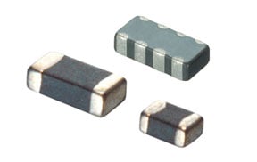
In this and subsequent parts, we will be discussing typical noise-suppression components. The first such component is the chip ferrite bead. These beads are ferrite bead inductors fabricated in the shape of chips which support surface mounting (SMD).
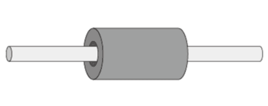
An example of the shape of a lead-type ferrite bead inductor is shown in Fig.1. The structure is a simple one, and with this shape a lead has been passed through the bead which is formed by the ferrite. This inductor does not have the lead wound around it as a regular coil does, but when current flows to its lead, magnetic flux is generated inside the ferrite bead. As a result, the ferrite bead functions as an inductor. Incidentally, the ferrite used here is made with materials which have a high loss at high frequencies, so in the high-frequency range the energy of the current is lost as a loss in the ferrite, enabling noise to be absorbed effectively.
Chip ferrite beads are made by fabricating these ferrite bead inductors into chips, and Fig. 2 shows their typical structure. Coil patterns are formed between the layers of the sheets of raw ferrite, and by a process of integration and firing, a 3-dimensional coil structure is produced.
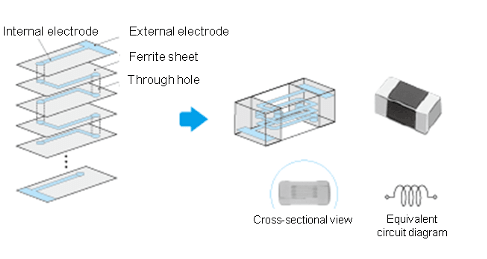
By fabricating the ferrite bead inductors as chips and by adopting a coil structure inside them, it is possible to achieve a higher impedance than that of the lead type of ferrite bead inductor that simply has the lead through it. (In reality, some chip ferrite beads have only a lead passing through the bead.) This structure is basically the same as that of a multilayer type of chip inductor, but the difference from an inductor lies in the fact that the ferrite material used is better suited to suppress noise.
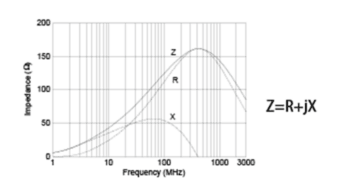
Fig. 3 shows an example of the impedance frequency characteristics of a chip ferrite bead. The basic principle involved is as follows: The impedance increases in proportion as the frequency rises, as in the case of inductors, so by connecting these beads in series in a circuit, they function as a low-pass filter. With regular inductors, the main characteristic among the impedance (Z) values is the reactance component (X). On the other hand, since chip ferrite beads use ferrite materials with a high loss in the high frequencies, the main characteristic in the high-frequency range is the resistance component (R). The reactance component is not accompanied by loss, but the resistance component is. This means that, compared with regular inductors, chip ferrite beads have better properties for absorbing noise energy, providing a higher noise-suppression effect.
Chip ferrite beads have been customarily standardized by impedance value at a frequency of 100 MHz. However, many kinds of products with the same impedance value are available. This is for the purpose of making it possible to select the sharpness of the impedance curve.
Fig. 4 shows an example of curve variations. Both the BLM18AG601SN1 and BLM18BD601SN1 are chip ferrite beads that have an impedance value of 600Ω at 100 MHz, but Fig. 4 shows that the BLM18BD601SN1 has a sharper impedance curve, whereas the BLM18AG601SN1 has a curve that rises more gently.
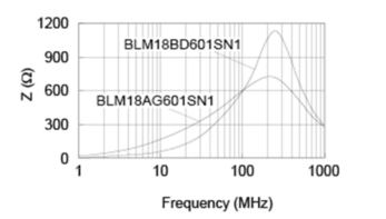
With the type whose impedance curve rises gently, the impedance begins to increase at a lower frequency level so noise can be suppressed across a wide frequency band from the very low frequencies to the high frequencies. However, if the signal frequency is relatively high, this frequency may also be attenuated. In contrast, with the type whose impedance curve rises sharply, the impedance increases only in the high-frequency range, so even if signals with a comparatively high frequency are used, noise can be suppressed without affecting the signals. For this reason, it is important to factor in the signal frequency and the frequency of the noise to be suppressed when selecting the chip ferrite beads.
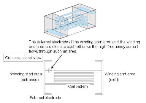
Fig. 3 showed the impedance frequency characteristics of chip ferrite beads, and this figure shows that the 400-500 MHz frequency area forms a boundary where the impedance value starts to drop off. This is due to the effects of the chip ferrite bead structure. As a basic rule, the impedance of an inductor continues to increase as the frequency rises. However, regular chip ferrite beads have areas inside them where the winding start (entrance) is close to the winding end (exit), as shown in Fig. 5. In such an area, electrostatic coupling (a state in which extremely small capacitors appear to be present) occurs so the high-frequency current passes through it, and the impedance of the inductor has less of an effect. In areas of electrostatic coupling, current tends to pass through more easily as the frequency increases, so the higher the frequency, the more the apparent impedance decreases.
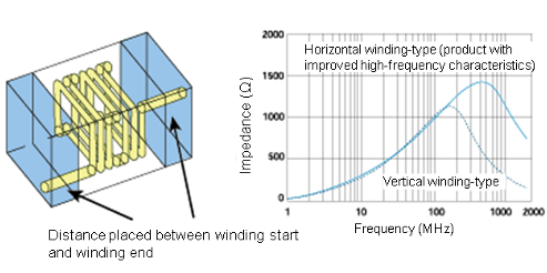
In order to resolve this problem, the structure where the winding starts and winding ends are positioned close together must be altered. Fig. 6 shows an example of a chip ferrite bead whose internal structure has been changed in order to improve the high-frequency characteristics. Whereas, in regular chip ferrite beads, the axis of the coil pattern runs perpendicularly (so-called "vertical winding"), the axis of the coil pattern for chip ferrite beads with improved high-frequency characteristics runs horizontally. As a result, by placing some distance between the coil winding start and winding end, the frequency at which the impedance starts to drop is significantly increased.
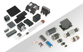
Chip ferrite beads come in many other variations--some support high currents and others have compact sizes, for example--and this variety enables users to select the ones optimally suited to the applications at hand.
Click here for information on BL□ series of chip ferrite bead products.
*The information presented in this article was current as of the date of publication. Please note that it may differ from the latest information.