Noise Suppression Products / EMI Suppression Filters / ESD Protection Devices
Noise Suppression Filter Guide
This article resumes the series from LC compound-type EMI filters.
It was previously introduced that using a combination of a capacitor and an inductor results in a steeper insertion loss curve than when using only a capacitor or an inductor. Figure 1 shows an image of these characteristics.
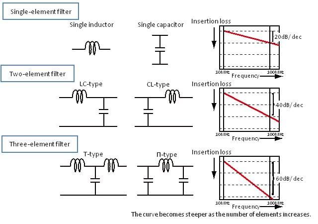
As shown in this figure, the slope of the filter insertion loss characteristics becomes steeper as the number of filter elements increases.
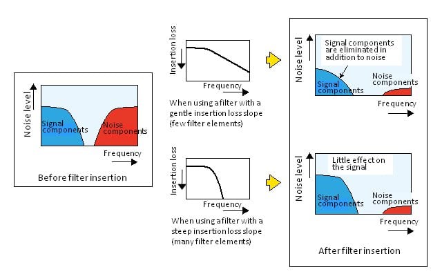
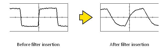
A steeper filter insertion loss characteristics slope helps prevent the signal from being adversely affected when the signal and noise frequencies are near each other. Figure 2 shows an example of when the signal frequency is comparatively high and near the noise frequency. When both frequencies are close and a filter with a gentle insertion loss slope is used, selecting constants that sufficiently reduce the noise also attenuates the higher harmonic components of the signal that are near the noise frequency. As a result, the signal waveform becomes corrupted as shown in Fig. 3. Conversely, when constants that do not affect the signal frequency are selected, the noise cannot be sufficiently reduced. On the other hand, when a filter with steep insertion loss characteristics is used, the signal and noise can be selectively separated, enabling suppression of the effect on the signal. For this reason, LC compound filters are used to implement noise countermeasures while minimizing the effect on the signal waveform in high-speed signal lines.
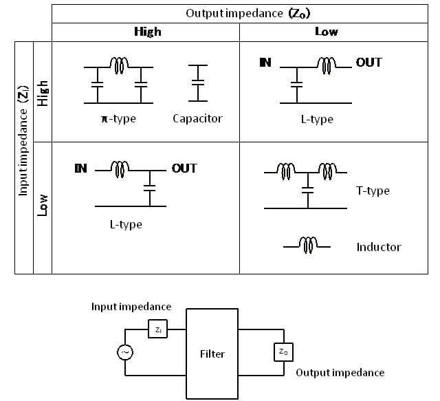
There are various types of LC compound filters that combine capacitors and inductors, depending on the combination. As introduced above, increasing the number of filter elements more effectively separates the signal and noise, but even when using the same number of elements, different configurations are possible such as T-type and π-type filters. The key point in deciding which type to use is the input/output impedance of the circuit in which the filter is to be inserted. Of the elements comprising an LC compound filter, reducing the impedance between the capacitors and the ground works to let noise escape to the ground side, so the noise reduction effects can be enhanced by locating capacitors near areas with high impedance. Conversely, inductors impede the passage of noise as the impedance increases, so the noise reduction effects can be enhanced by locating inductors near areas with low impedance. In this manner, the key point when selecting an LC compound filter is whether the impedance before and after the filter is high or low. Figure 4 shows examples of these configurations.
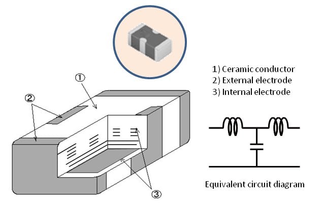
As mentioned above, LC compound filters feature the ability to set steep insertion loss characteristics, so they are often used when the signal frequency is comparatively high and near the noise frequency. Previously these filters were often used for applications such as the analog RGB interfaces of computers, and use is recently increasing to remove mobile phone carrier wave and TV broadcast band noise in the interface lines of the LCD modules and camera modules used inside mobile phones. Miniaturization is an extremely important issue for mobile phones, so the LC compound filters used for these applications use multilayer technology. In addition, multiple signal lines are arranged in parallel in these locations, so array-type filters that incorporate four circuits into a single package are often used.
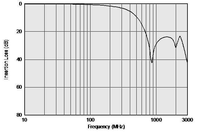
In addition, filters with multiple self-resonant frequencies are also provided for use in mobile phones to enable noise countermeasures that emphasize multiple frequency bands such as the 800 MHz band and the 2 GHz band.
*The information presented in this article was current as of the date of publication. Please note that it may differ from the latest information.