Noise Suppression Products / EMI Suppression Filters / ESD Protection Devices
Noise Suppression Filter Guide
We plan to discontinue the production of some of the products (DLW44SN***SK2 series) introduced in this article.
Electronic devices are generally made up of multiple semiconductor and functional blocks that each must be supplied with power at the designated voltage.
In many cases, the required voltages are all different, and must be converted using a DC-DC converter (circuit that converts the power supply to the voltage required for the operation of electronic components).
Due to size and electrical performance considerations, switching DC-DC converters are often used in such cases. However, attention must be paid to the noise caused by switching. Some type of noise countermeasure is required if the noise regulation standards are not met.
This article introduces examples of countermeasures using a common mode choke coil to deal with power supply noise.
For this noise countermeasure example, we prepared a typical non-isolated, step-down type (5 V to 1.8 V, Pout = 27 W) DC-DC converter with a switching frequency of 500 kHz.
The goal here is to support the CISPR22 class B general device standard (devices used in ordinary homes and light industrial environments). Effective noise countermeasures were implemented after determining whether the noise mode was primarily differential mode or common mode.
See the following link for an explanation of the noise modes.
「Basics of Noise Countermeasures [Lesson 6] Common mode choke coils」
The common mode voltage (noise terminal voltage) was measured for one line with respect to ground using an artificial mains network (AMN). When the noise terminal voltage is measured under the initial conditions, we can see that a noise spectrum occurs at multiples (frequency is converted to n multiples) of the 500 kHz switching frequency. (Figure 1)
Before proceeding with the noise countermeasure, we performed mode separation using Delta-LISN (Line Impedance Stabilization Network) in order to determine whether the noise mode was primarily differential mode or common mode. As shown in Figure 2, it is clear that the noise in this case is primarily differential mode noise.
As a result, the noise level was significantly decreased when the EMIFIL BNX029-01 block-type filter was used, due to its highly effective countermeasures for differential mode noise. (Figure 3)
After implementing the countermeasure described above, we evaluated the radiation noise at 3 m to measure the intensity of the field emitted into the space, and discovered radiation noise that significantly exceeded the CISPR22 class B noise tolerance (Figure 4).
When the radiation path was investigated, it was discovered that the input power supply cable of the DC-DC converter was acting as an antenna and radiating noise into the surrounding space.
The BNX029-01 is able to remove differential mode noise across a wide frequency band from 100 kHz to 1 GHz, so the remaining noise was presumed to be common mode noise.
When a PLT10HH9016R0PN common mode choke coil was inserted to deal with the common mode noise, the level of radiation noise significantly improved to meet the CISPR22 class B noise tolerance. As a result, we learned that the radiation noise was primarily common mode noise (Figure 5).
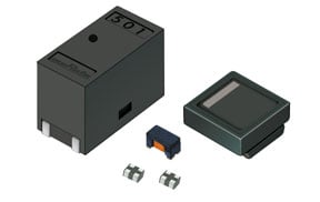
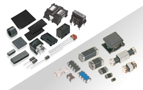
At Murata Manufacturing Co., Ltd., we maintain a wide variety of component sizes and characteristics to provide the optimal components for customer applications (Table 1).
We plan to discontinue the production of DLW44SN***SK2.
Table 1. Lineup of common mode choke coils
Product name | Size | Common mode | Rated current *1 | Rated voltage |
|---|---|---|---|---|
4.0x4.0mm | 100Ω to 2400Ω | 3.1A to 1.1A | 60Vdc | |
5.0x5.0mm | 100Ω to 1400Ω | 6A to 2A | 50Vdc | |
5.0x5.0mm | 100Ω to 500Ω | 5.6A to 3.1A | 80Vdc | |
12.9x6.6mm | 45Ω to 100Ω | 18A to 15A | 300Vdc | |
400Ω to 1000Ω | 10A to 6A | 100Vdc |
*1 With regard to the rated current, derating is configured, so please see the detailed specifications for each product.
*2 The operating temperature range differs for each product type, so please see the detailed specifications for each product.
Search from the application.
・For Power line - Non Automotive Grade -
・For Power line - Automotive Grade -
When implementing noise countermeasures, it is extremely important to determine whether the noise mode is common mode or differential mode. At Murata, we maintain common mode choke coils for power lines in every size, and these have the high rated current and high insertion loss to provide the optimal noise suppression products for your power supply circuits.
Tadashi Tanaka
Product Engineering Section 3, Product Engineering Department, EMI Filter Division
Murata Manufacturing Co., Ltd.
The information presented in this article was current as of the date of publication. Please note that it may differ from the latest information.