Robot Emission Suppression Measures-2 (2/4)
INDEX
2. Radiation noise evaluation of commercial robots
3. Pseudo-robot emission suppression (conducted noise)
4. Pseudo-robot emission suppression (radiation noise)
5. (1) Case example of brush motor noise
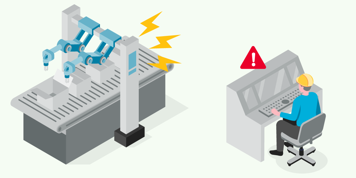
Thus far, we have introduced a case example of radiation noise suppression using a commercially available articulated robot, but it is expected that there will be various other case examples in which noise becomes a problem.
Here, we introduce three case examples of noise problems that are expected in robots.
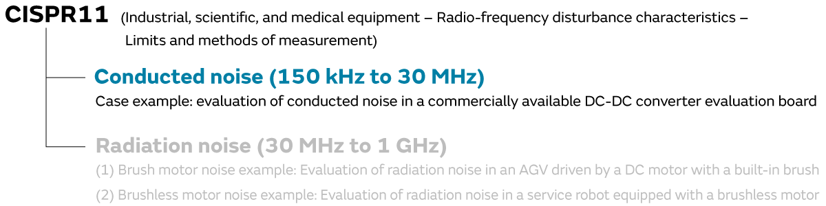
3. Pseudo-robot emission suppression (conducted noise)
3-1. (Case example) Evaluation of conducted noise in a commercially available DC-DC converter evaluation board
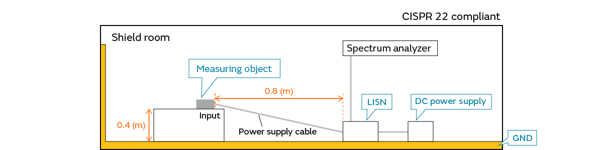
The conducted noise regulated by CISPR 11 is measured with a common mode voltage leaking into an AC power supply line.
Here, it appears that the noise conducted to the AC power supply line is often caused by the switching of the DC-DC converter.
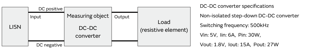
We used the DC-DC converter evaluation board to evaluate the noise.
The measured conducted noise is as follows. A noise spectrum was observed at frequencies that are a multiple of the switching frequency of 500 kHz. There is noise that exceeds the noise tolerances for CISPR 11 Class A Group 1 (industrial environment). This result is not unusual, and in equipment that does not suppress noise (switching noise) caused by DC-DC converter switching, there are many cases in which the switching noise is conducted to the AC power supply line and causes problems.
When public noise standards are applied to robots going forward, it will become necessary to suppress noise that is conducted to the AC power supply line in robots.
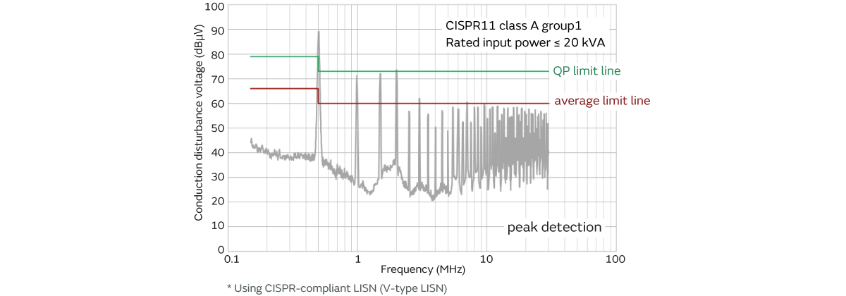
- A noise spectrum is generated at frequencies that are a multiple of the switching frequency of 500 kHz.
- Noise source: DC-DC converter (switching noise)
- Path: noise is conducted to the input DC power supply line (DC positive, negative)
3-2. Conducted noise mode separation (separated into differential/common mode)
Because we verified that there is a need to suppress the conducted noise (suppression is required to meet the noise specifications), we performed a mode separation of the conducted noise to verify the noise tendencies. The mode separation mentioned here is separated into differential mode voltage and common mode voltage. This mode separation is performed using a Delta-type LISN (Delta-type line impedance stabilization network).
*If we look at the CISPR noise specifications, the use of a V-type LISN is stipulated, and compliance with the noise specifications cannot be determined in the evaluation results with the Delta-type LISN. The robot noise specifications are being formulated, and it is thought that the V-type LISN will probably be used. In order to understand the noise tendencies, here we are using a Delta-type LISN instead of the V-type LISN used in the standard.
As a result of performing the mode separation, we can see that the differential mode noise is high in all frequency bands. Therefore, we need to suppress the noise with a filter that can control the differential mode.
*Because the differential mode noise is dominant in this case example, the conducted noise cannot be controlled even if a filter such as a common mode choke coil, which can control only the common mode, is used.
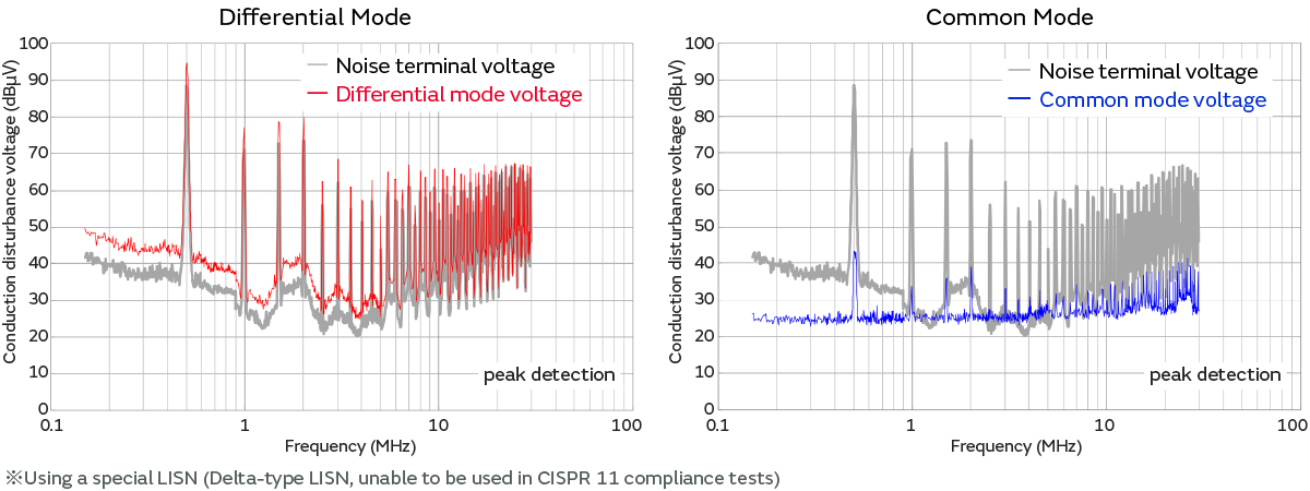
- All frequency bands are affected by the differential mode voltage.
- We can see that differential mode noise suppression is needed.
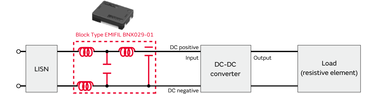
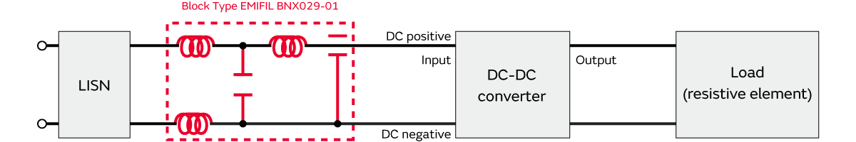
The differential mode was dominant in all frequency bands of the power supply circuit conducted noise in this case example. A Block Type EMIFIL (High-Current, High-Attenuation) BNX029-01 is used as the filter configuration that can control this differential mode voltage.
(Reason for selecting the BNX Series)
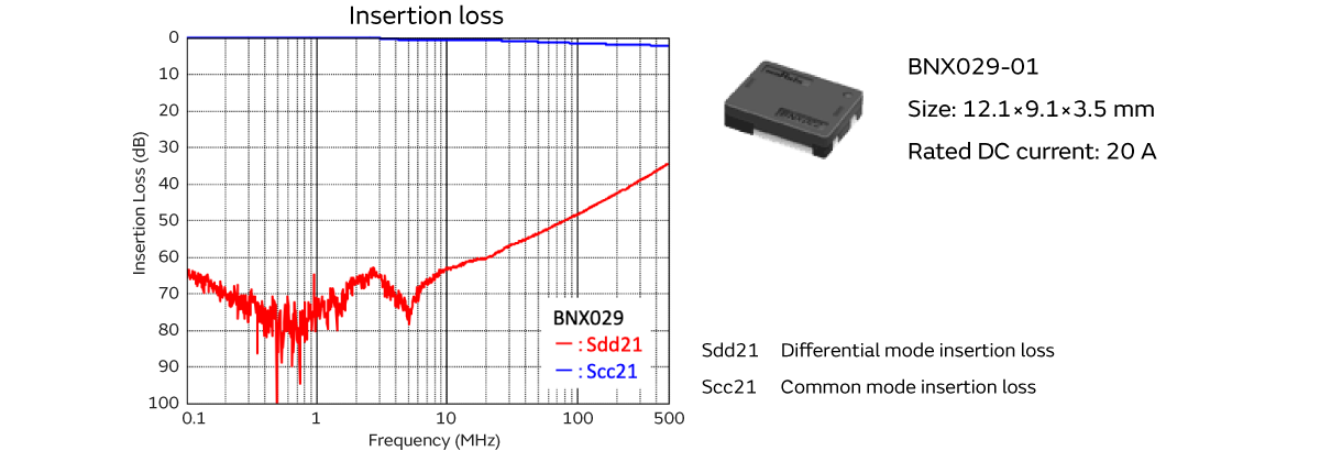
The LC π-type filter is a representative filter configuration that controls the differential mode voltage in the 150 kHz to 30 MHz frequency band. When configuring this LC π-type filter, one may consider configuring it with a 470 uF electrolytic capacitor and a 1 mH inductor, for example. On the other hand, components such as electrolytic capacitors are not desirable in robots and other power supplies from the perspective of conserving space, reducing the number of components, and high reliability. Therefore, we selected the BNX029-01 Block Type EMIFIL (High-Current, High-Attenuation) as a filter that can satisfy the requirements above.
By inserting the BNX into the DC line, we were able to significantly control the differential mode voltage in all frequency bands.
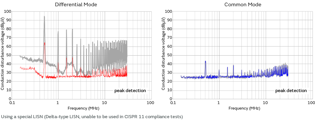
- The differential mode voltage can be significantly controlled in all frequency bands.
We measured the conducted noise before and after the noise suppression with a V-type LISN, which is expected to be used in the noise regulations.
By inserting the BNX into the DC line, we were able to satisfy the CISPR 11 noise tolerances in all frequency bands. Performing mode separation on the conducted noise and suppressing the mode that is causing the noise in a concentrated manner in this way enables effective noise suppression.
By using this kind of suppression method, you can select a filter configuration without backtracking in addition to being able to shorten the time spent on suppression. Moreover, because you can implement suppression based on data rather than uncertain information such as experience or intuition, this enables noise suppression with a minimum amount of effort regardless of the power supply circuit.
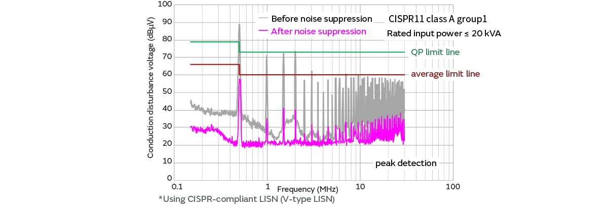
- Satisfying the noise tolerances by controlling the differential mode.
3-3. Summary of DC-DC converter noise suppression
- Continue reading:Robot Emission Suppression Measures-3 (3/4)
Related articles
- Electromagnetic Interference from Industrial Equipment: Effects on Wireless Communication and Modern Mitigation Strategies
- Immunity improvement method for industrial equipment
- Murata Manufacturing Presents Solutions to Realize a Safe and Comfortable Car Society at the Automotive Engineering Exposition