Robot Emission Suppression Measures-4 (4/4)
INDEX
2. Radiation noise evaluation of commercial robots
3. Pseudo-robot emission suppression (conducted noise)
4. Pseudo-robot emission suppression (radiation noise)
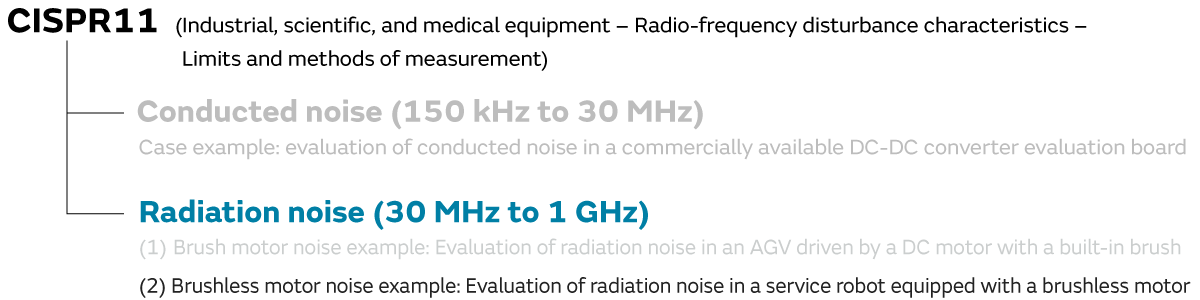
5. (1) Case example of brush motor noise
6. (2) Case example of brushless motor noise
To continue, we introduce (2) a case example of brushless motor noise.
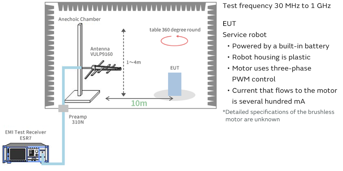
6-1. (Case example) Evaluation of radiation noise in a service robot equipped with a brushless motor
As a case example of the radiation noise of a brushless motor, we introduce an example of radiation noise using a service robot. Furthermore, because AC power is sometimes supplied to service robots in a shared pole-mounted transformer or other public distribution network, the noise tolerances applied Class B.
These are the radiation noise evaluation results before the noise suppression.
It is believed that in many robots radiation noise is prone to becoming a problem in the 30 MHz to 100 MHz frequency band (200 MHz in this case example).
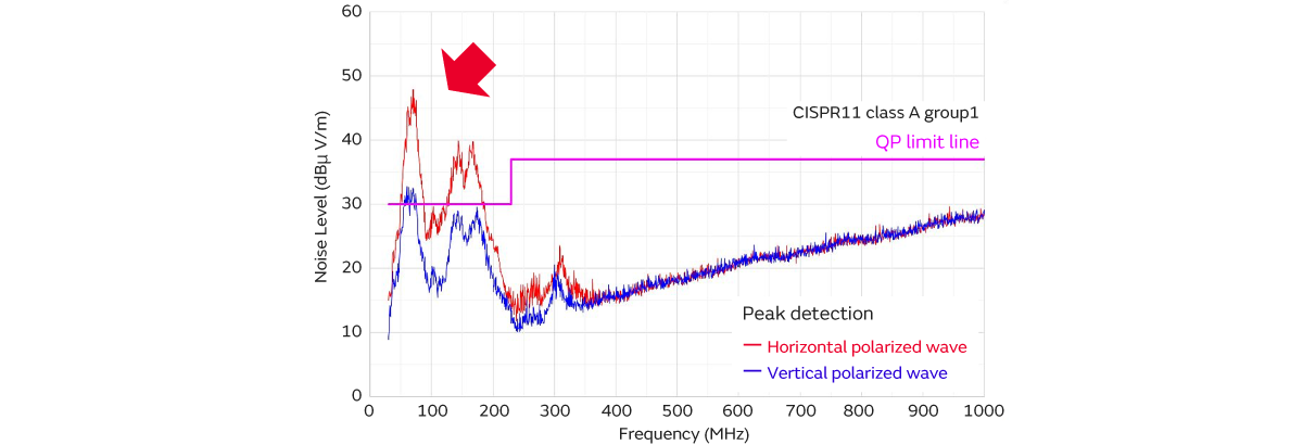
- Noise spectrum observed between 30 MHz and 200 MHz.
A brushless motor was adopted as the motor for the evaluation equipment.
A motor driver circuit is required to operate the brushless motor. Typically, the driver circuit of a brushless motor adopts a three-phase PWM control circuit.
This control circuit is composed of two switching elements for each phase (total of six), and each phase applies a continuous current to the motor by turning on and off at the right time.
This is not limited to robots, but switching noise is generated, because the motor driver circuit is composed of switching elements. When the switching noise is conducted to the cables, the noise from the cables radiates into the surrounding space, because the cables used in the robots are insulating layer cables with no shielding.
In addition, because noise is also conducted to the winding coils inside the motor, noise also radiates from the motor unit.
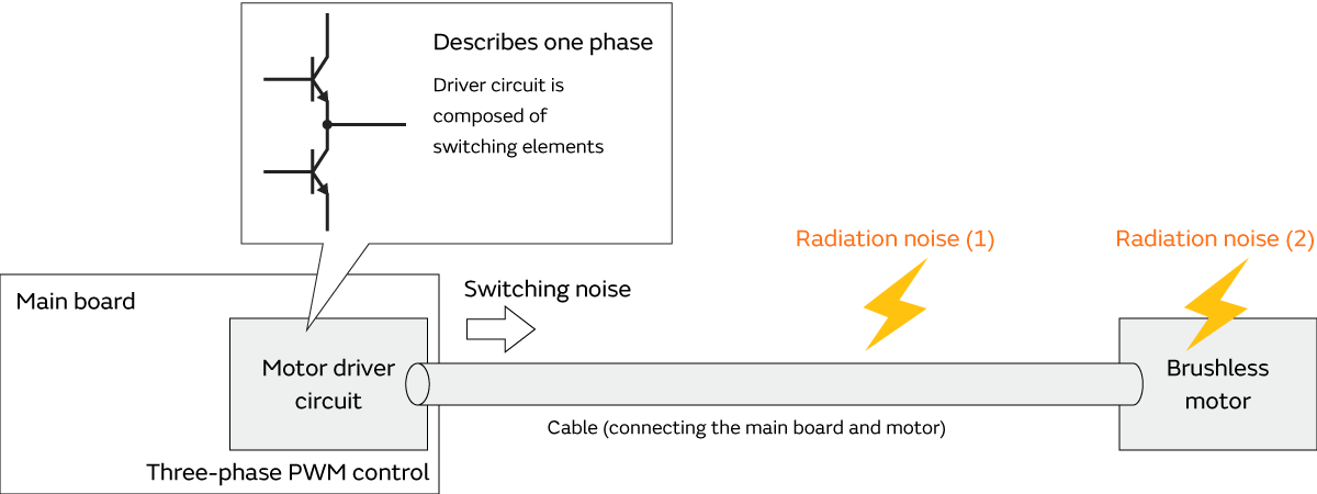
- Noise source: motor driver circuit switching (switching noise)
- Paths: Noise is conducted to the cable that connects the board and the motor
- Radiation antenna:
(1) Cable that connects the board and the motor
(2) Motor unit (winding coils inside the motor)
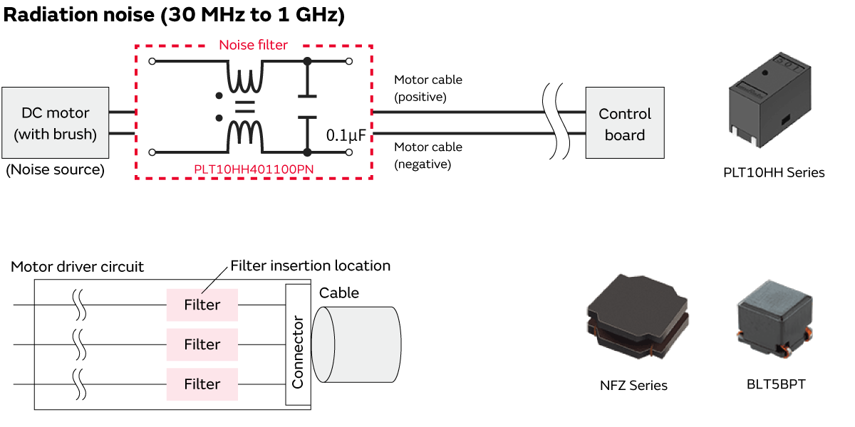
The switching noise generated by the motor driver circuit is conducted to and radiates from the cables and motor unit.
As a measure to suppress this noise, a noise filter is inserted close to the connector. A filter with insertion loss between 30 MHz and 200 MHz (up to 300 MHz) is selected for use here.
(Ex.) BLM31KN471SN1, NFZ Series, BLT5BPT, etc.
The rated current of the filter to be inserted in each line of the motor should be noted here. If the current during normal motor operation is 1 (A), it would be desirable to select a component with three to five times the rated current.
(Reason)
If the motor locks for some reason while running, an instantaneous spike current may flow. A component that will not malfunction even if such an instantaneous current flows must be selected.
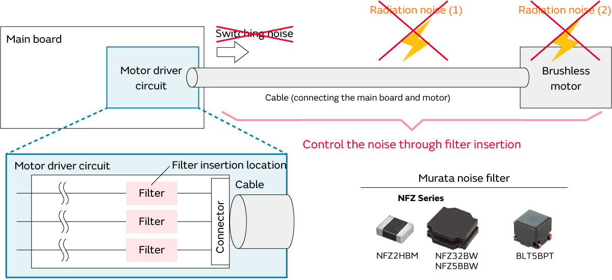
- Do not allow the ( switching ) noise generated by the driver circuit to be conducted to the cables.
NFZ Series (NFZ2HBM/NFZ32BW/NFZ5BBW)
6-2. Noise filter-based suppression
We investigated the radiation noise before and after the filter insertion. A NFZ2HBM4R4SN10 filter was used.
A noise margin of 5 dB or more with respect to the standard tolerance was ensured by inserting the filter. In this way, the radiation noise can be effectively controlled by using a filter in the noise-conducting path.

Noise filter (NFZ2HBM4R4SN10)
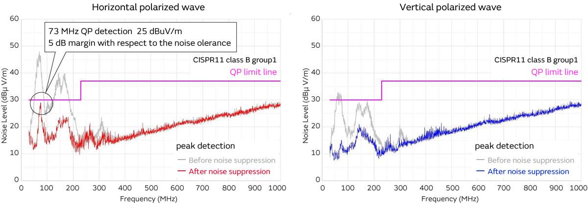
- Radiation noise can be effectively controlled by inserting a filter.
7. Summary
We introduced examples of conducted noise and radiation noise suppression as examples of robot emission suppression. Regarding radiation noise, we introduce examples of brushed and brushless motors. In either case, we were able to investigate the noise generation source, conducting path, and radiation locations to suppress the noise by setting the appropriate noise filter in the conducting path.
7-1. Robot emission suppression proposal CISPR11
7-2. Noise suppression products proposed by Murata
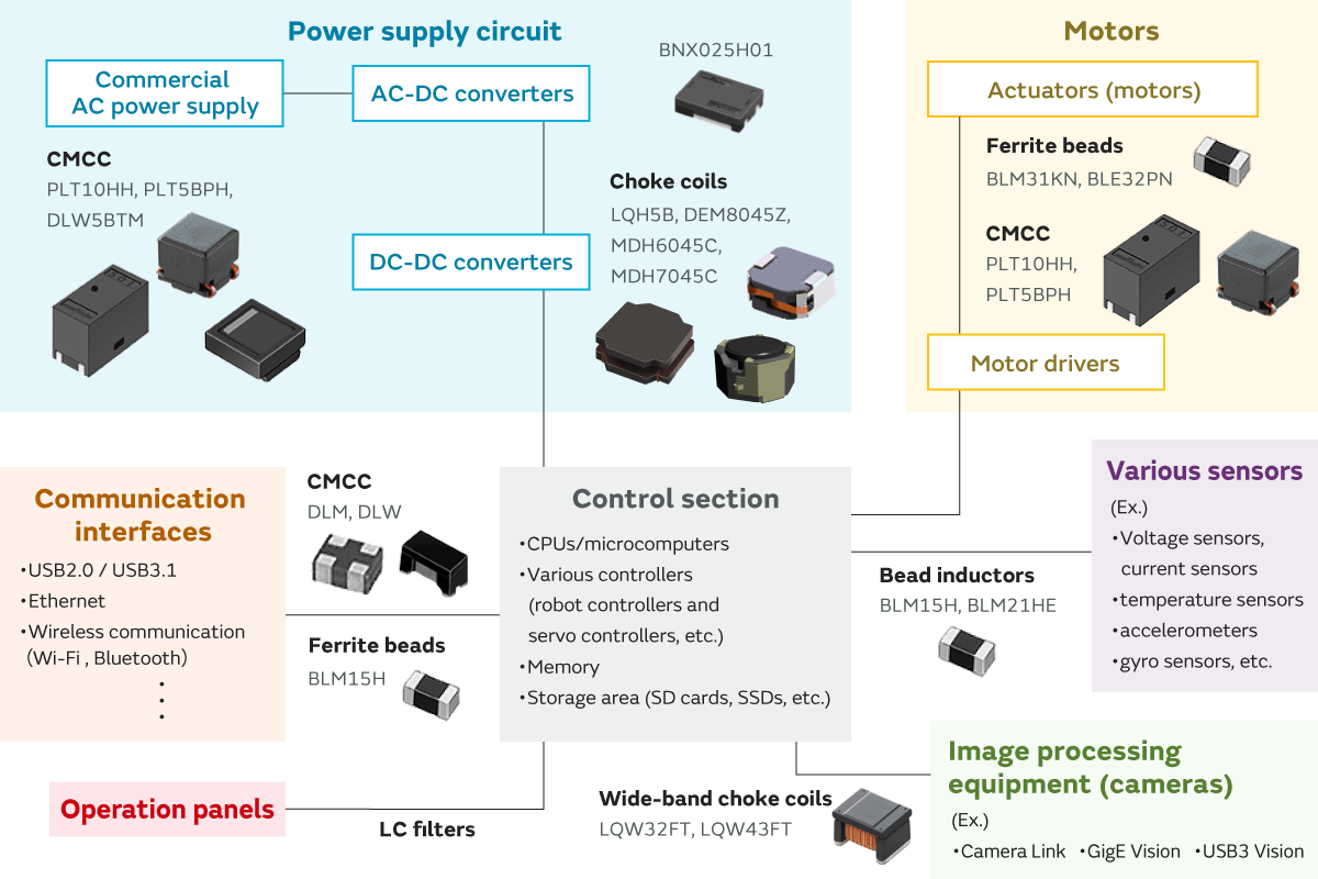
CMCC (PLT10HH/PLT5BPH/DLW5BTM)
Choke coils (LQH5B/DEM8045Z/MDH6045C/MDH7045C)
Ferrite beads (BLM31KN/BLE32PN)
Ferrite beads (BLM15H)
Bead inductors (BLM15H/BLM21HE)
Wide-band choke coils (LQW32FT/LQW43FT)
Related articles
- Electromagnetic Interference from Industrial Equipment: Effects on Wireless Communication and Modern Mitigation Strategies
- Immunity improvement method for industrial equipment
- Murata Manufacturing Presents Solutions to Realize a Safe and Comfortable Car Society at the Automotive Engineering Exposition