Robot Emission Suppression Measures-3 (3/4)
INDEX
2. Radiation noise evaluation of commercial robots
3. Pseudo-robot emission suppression (conducted noise)
4. Pseudo-robot emission suppression (radiation noise)
5. (1) Case example of brush motor noise
4. Pseudo-robot emission suppression (radiation noise)
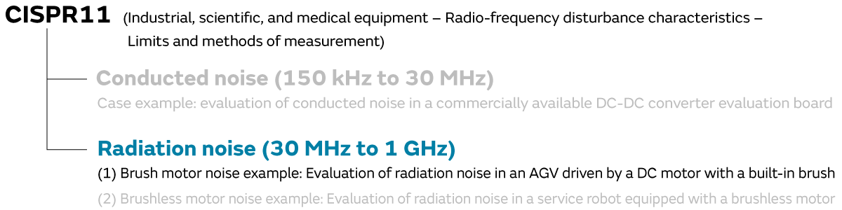
As the second case example of robot emission suppression, we introduce the case example of radiation noise suppression evaluated between 30 MHz and 1 GHz. In this part, we discuss two case examples concerning (1) brush motor noise and (2) brushless motor noise.
5. (1) Case example of brush motor noise
5-1. (Case example) Evaluation of radiation noise in an AGV driven by a DC motor with a built-in brush
As a case example of the radiation noise of a brush motor, we investigated radiation noise in an AGV (Automated Guided Vehicle) driven by a DC motor with a built-in brush.
In this investigation, we laid down magnetic tape in a circle on the floor of an anechoic chamber and had the AGV run in a circle on top of that magnetic tape to measure the noise.
The AGV is driven by a DC motor with a built-in brush.
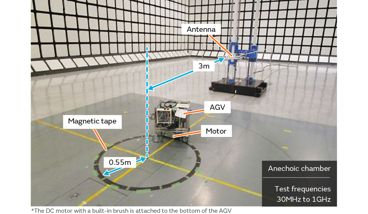
- The AGV ran in a circle over the circular magnetic tape.
- The CISPR 11 measurement environment was referenced to evaluate the radiation noise in an equipment layout based on the expected actual use environment.
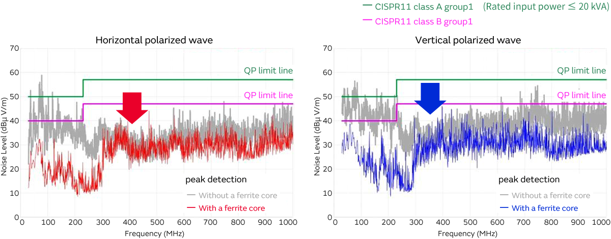
We investigated the radiation noise before noise suppression.
A noise spectrum was observed in a broad frequency band from 30 MHz to 1 GHz.
In addition, a noise spectrum exceeding the noise tolerances was observed in some sections.
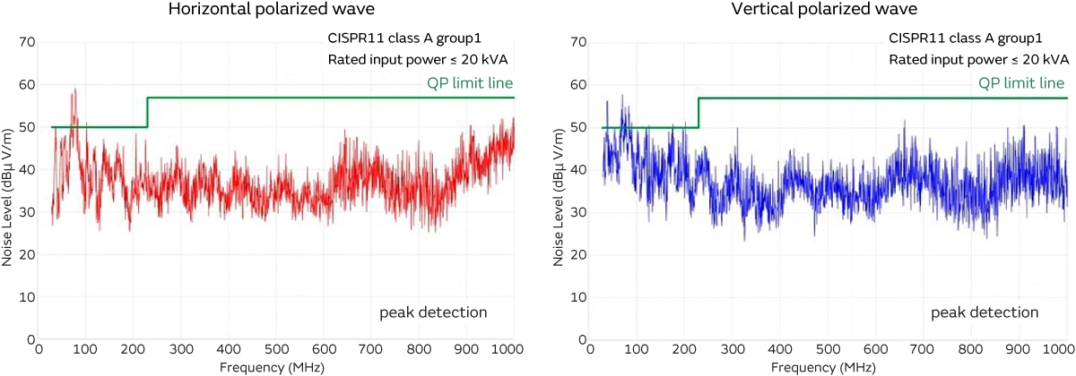
- Needle-shaped noise spectrum observed across a broad frequency band
5-2. Radiation antenna investigation (noise isolation)
We investigated the radiation noise generation mechanism in a manner similar to the commercial robot investigation.
The radiation antenna investigation is extracted and shown here.
- Noise source: brushed DC motor discharge noise
- Path: The motor discharge noise is conducted to the cable
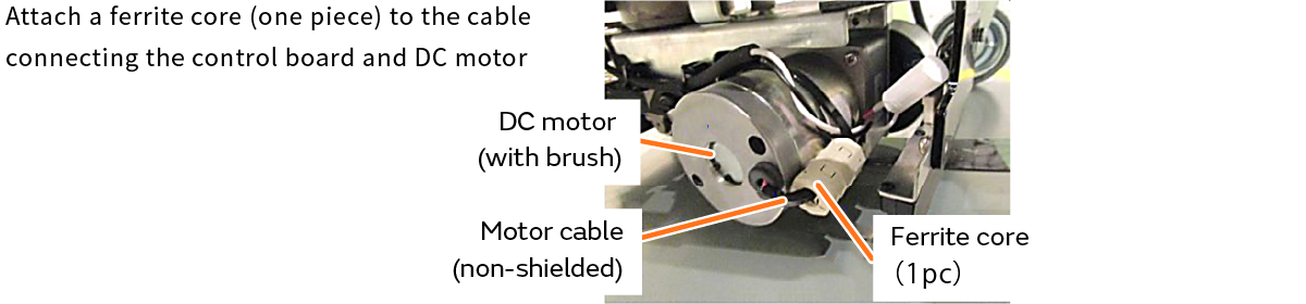
- Radiation antenna: cable which connects the control board and the motor
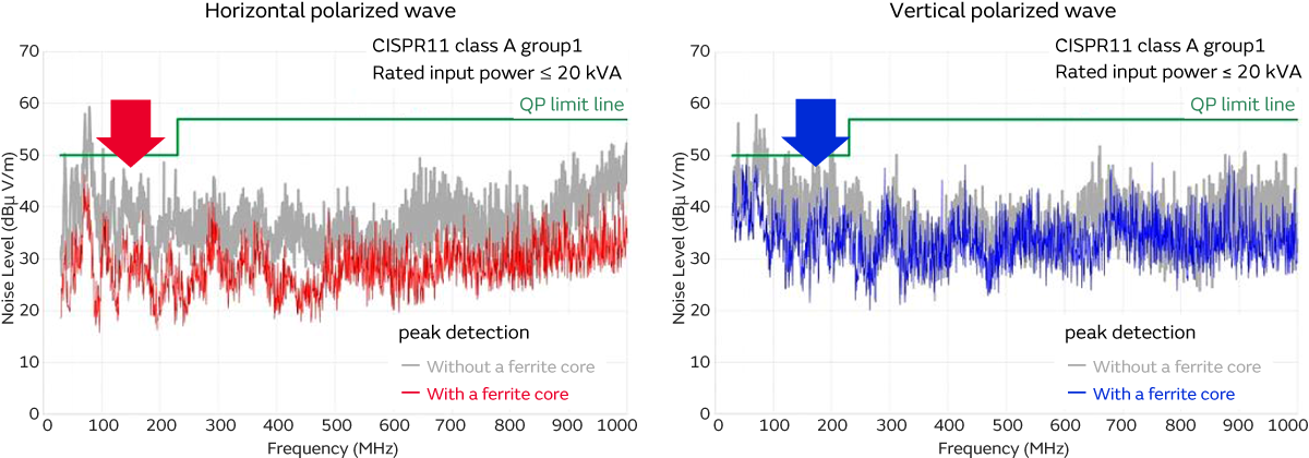
- The level of radiation noise decreases due to the ferrite core.
When one ferrite core was attached to the cable connecting the motor and the control board, the radiation noise spectrum decreased in all frequency bands. As a result, the noise source, conducting path, and radiation antenna can be considered as shown in (1) through (4) in the figure below.
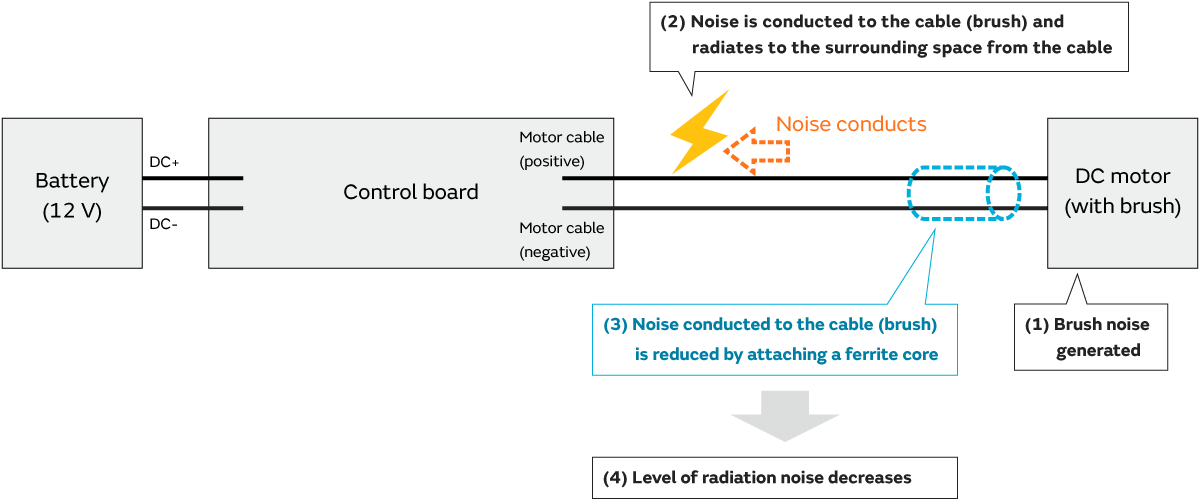
Brush noise is generated when the brushed motor runs. This brush noise is always generated due to the operating principle of the brushed motor. This brush noise is conducted to the cable shown in (2). Most of the cables used in robots are vinyl coated cables, and shielded cables are rarely used. In other words, when noise is conducted to vinyl coated cables, it is radiated into the surrounding space.
This section explains the radiation antenna investigation that was indicated earlier. When a ferrite core is attached to the cable connecting the motor and control board (cable shown in (2)), the brush noise generated by the motor is inhibited by the ferrite core, which makes it difficult for the noise to flow into the cable. (*Because the cable impedance increases with the ferrite core, it is difficult for the noise to conduct.)
Since it is difficult for the noise to conduct to the cable shown in (2), the noise radiating from the cable decreases.
In this case example, the noise source is the brush noise of the brushed motor, and the radiation antenna was the cable shown in (2).
5-3. Brush noise suppression example
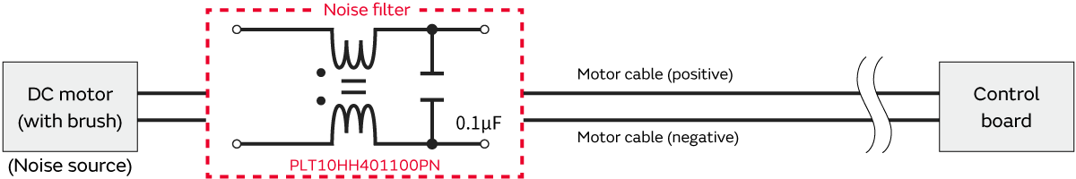
This section introduces a case example of suppressing brush noise with a filter.
This case example used a common mode choke coil (PLT10HH) and an X capacitor (0.1 uF).
We investigated the noise before and after the suppression with this filter configuration.
By inserting the filter, we are able to reduce the noise spectrum in all frequency bands.
In addition, we were also able to satisfy the noise tolerances and effectively control the radiation noise with a small number of components.
- Do not allow the noise generated by the motor (brush) to conduct to the cables.
- Radiation noise significantly decreases.
5-4. Summary of brushed motor radiation noise suppression
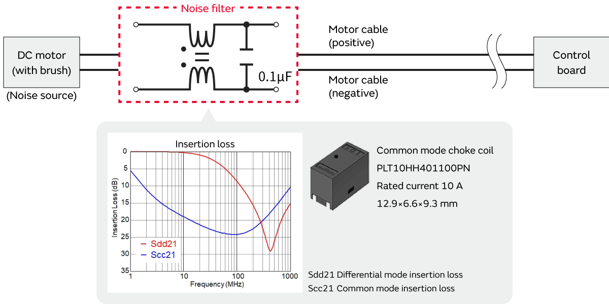
Common mode choke coil (PLT10HH401100PN)
- Continue reading: Robot Emission Suppression Measures-4 (4/4)
Related articles
- Electromagnetic Interference from Industrial Equipment: Effects on Wireless Communication and Modern Mitigation Strategies
- Immunity improvement method for industrial equipment
- Murata Manufacturing Presents Solutions to Realize a Safe and Comfortable Car Society at the Automotive Engineering Exposition