Noise Suppression Products / EMI Suppression Filters / ESD Protection Devices
Noise Suppression Filter Guide
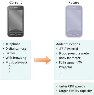
Recently, many functions such as digital cameras, games, web browsing, and music playback have been added to the telephone functions of compact mobile devices such as smartphones, and it is expected that even more diverse functions will be added in the future. In addition, it is anticipated that high-speed data communications functions such as LTE will become popular, and the exchange of movies and other large-volume data will also increase (see figure 1).
As CPU speeds increase and LTE communications are adopted, both power consumption and battery capacities are increasing, so the main boards on which electronic components are mounted are tending to become smaller.
In addition, the number of electronic components mounted on boards is also tending to increase as functions become more advanced.
In particular, tens of MLCCs (Multi-Layer Ceramic Capacitors) are sometimes used in the power supply circuit of a single application processor IC that processes large-volume data.
Based on the above background and technical trends in smartphones, the following characteristics are required of MLCC used in IC power supplies.
By making optimal use of the latest compact and large-capacity low-ESL capacitors as power supply MLCCs, the number of MLCCs can be reduced by half or more and the mounting area occupied by the MLCCs can also be greatly reduced as shown in figure 2.
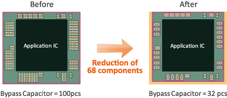
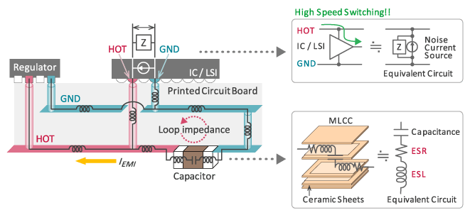
Figure 3 shows the connections between an IC/LSI power supply line and the MLCC used in that line.
As IC/LSI switching speeds increase, these ICs/LSIs are tending to become sources of noise.
Large numbers of MLCC are used as bypass capacitors as shown in figure 3 as countermeasures against high-frequency noise and to suppress supply voltage fluctuation.
In Figure 3, the impedance generated by the current loop that passes from the HOT pin of the IC/LSI through the MLCC and then returns to the GND pin of the IC/LSI is called the loop impedance. Since the supply voltage fluctuation that occurs between the HOT and GND pins of the IC/LSI depends on the size of this loop impedance, there is an increasing need to suppress loop impedance in order to suppress supply voltage fluctuation. The impedance of the MLCC comprises a part of this loop impedance.
Normally, in order to suppress loop impedance, large numbers of MLCCs are connected in parallel to reduce the total impedance by the parallel effect. The structure and equivalent circuit of the MLCCs used here are shown in the lower part of figure 3, and although they are capacitors, they also have minute levels of equivalent series resistance (ESR) and equivalent series inductance (ESL). Of these, ESL is a factor increasing the loop impedance at high frequencies.
As described below, the low-ESL capacitors introduced in this article are a type of MLCC created in a manner to reduce the ESL. Loop impedance can be reduced by using these low-ESL capacitors as bypass capacitors. In addition, the number of components used in parallel can be reduced by replacing MLCC with low-ESL capacitors, which enables greatly reducing both the number of components and the mounting area.
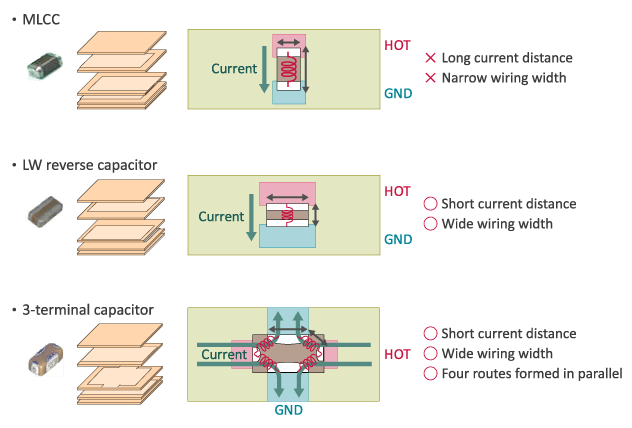
The structures and features of low-ESL capacitors are explained below. There are two types of low-ESL capacitors: LW reverse capacitors and 3-terminal capacitors.
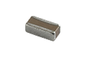
The center area of figure 4 shows the structure of an LW reverse capacitor. The length (L) and width (W) directions are the reverse of a normal-type capacitor, and the external electrodes are located on the lengthwise sides.
The ESL of MLCCs generally tends to increase in accordance with the distance that the current flows, and decrease as the width becomes wider, so the LW reverse capacitor structure realizes low ESL by shortening the distance and widening the width over which the current flows.
Next, the structure of a 3-terminal capacitor is described (lower area of figure 4). The internal electrode structure of a 3-terminal capacitor has alternately overlapping HOT through electrodes and GND through electrodes. This means that when a current flows in the bias direction, the current flows over a short length and a wide width, so the ESL is low. In addition, 3-terminal capacitors form four routes through which current flows, and realize even lower ESL due to this parallel effect. Furthermore, the current flows to the GND directions, that is to say the up and down directions in the figure below. The mutual inductance generated by this current realizes low ESL.
The graph in figure 5 compares the impedance frequency characteristics of a normal MLCC with those of the low-ESL capacitor types of an LW reverse capacitor and a 3-terminal capacitor. Each type has the same capacitance of 1 uF, so they exhibit roughly the same characteristics in the frequency band below their respective self-resonance points. However, in the frequency band above the self-resonance point, the impedance of each type differs greatly due to the differences in ESL.
As shown in figure 5, the LW reverse capacitor has 1/3 the ESL and the 3-terminal capacitor 1/10 the ESL of a normal MLCC. However, it should be noted that this performance comparison is for standalone capacitors, and capacitors are actually used mounted on a board, so the loop impedance includes the board and via-hole inductance components in addition to the capacitor ESL.
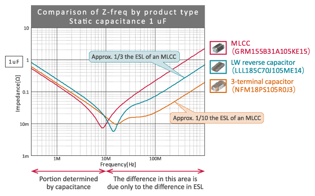
Figure 6 compares the impedance frequency characteristics of the latest compact and large-capacity low-ESL capacitors and MLCC. The impedance at high frequencies of an LW reverse capacitor (1.0 × 0.6 mm size; 4.3 uF) is equal to the impedance of two MLCC (0.6 × 0.3 mm size, 1 uF), so two MLCCs can be replaced by a single LW reverse capacitor.
The impedance at high frequencies of a 3-terminal capacitor (1.0 × 0.5 mm size; 4.3 uF) is equal to the impedance of four or more MLCCs. In theory, therefore, four or more MLCCs can be replaced by a single 3-terminal capacitor.
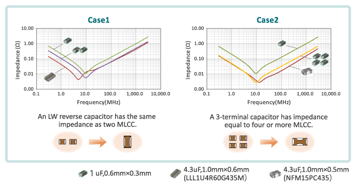
Figure 7 explains the principle of reducing the number of MLCCs by using 3-terminal capacitors.
For convenience, this example uses the simple structure of a via-hole, wiring, and a capacitor.
① shows an example of using an MLCC as a bypass capacitor. The loop impedance in this case is the total value of the impedance due to the inductance components of the via-hole, wiring, and MLCC.
② shows the case when a single MLCC is replaced by a single 3-terminal capacitor. The 3-terminal capacitor has a lower ESL than the MLCC, so the total loop impedance value is reduced. Therefore, a reduction in the voltage fluctuation due to loop impedance can be expected.
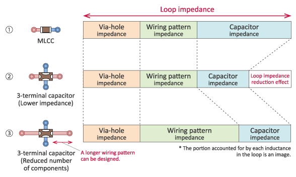
Figure 8 shows another method of using a 3-terminal capacitor.
For example, when replacing bypass capacitors with a 3-terminal capacitor, assuming the same loop impedance (the same voltage fluctuation level) as for the MLCC, the wiring design can be lengthened by an amount equivalent to the difference in the capacitor impedance. This extra wiring length can be used to cover multiple power supply pins with a single 3-terminal capacitor. In this case, the use of a 3-terminal capacitor enables combining of multiple bypass capacitors to reduce the number of components as shown in figure 8. The wiring length increases so the wiring inductance also increases, but the capacitor inductance is reduced, so the total impedance does not change.
However, when the wiring is thin and/or long and exceeds the capacitor ESL component, there is no effect. Therefore, to reduce the wiring inductance component it is recommended to increase the wiring width and to connect power supply via-holes on the bypass capacitor mounting surface to increase the parallel effect.
Currently, the reference designs of application IC for some smartphones include 100 or more 0603-size, 1 uF MLCCs as power supply bypass capacitors.
Of these, there are cases where 10 or more bypass capacitors are used in parallel in a number of core power supply lines. In addition, it is also recommended to use two or three capacitors in parallel in many other power supply lines.
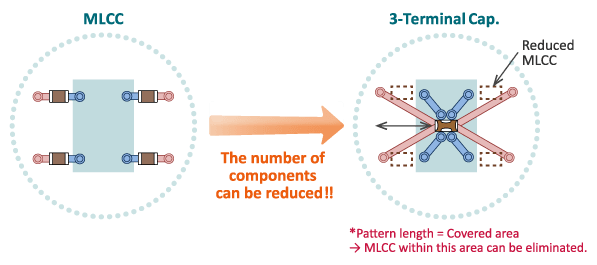
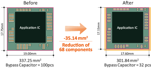
Figure 9 shows an example of reducing the number of components by changing these capacitors from MLCCs to low-ESL capacitors. By using low-ESL capacitors as shown in figure 9, it was found that the number of MLCCs can be reduced from 100 in the original design to just 32, while maintaining the same loop impedance. That is to say, the total number of MLCCs can be reduced by 68. In addition, by changing to low-ESL capacitors, the area occupied by the application IC and its peripheral capacitors can be reduced by approximately 35 m㎡.
By making optimal use of the latest compact and large-capacity low-ESL capacitors, the number of MLCCs used in IC power supplies can be reduced by half or more, enabling greatly reduced mounting area occupied by MLCCs. In the future we intend to continue commercializing compact and large-capacity low-ESL capacitors to contribute to further reducing the number of components and the mounting area.
Written by: Kazuki Kato, Product Development Dept.2, Fukui Murata Manufacturing Co., Ltd.
The information presented in this article was current as of the date of publication. Please note that it may differ from the latest information.