Capacitor Guide
Insulation resistance and leakage current of ceramic capacitor
Since the electrodes of the capacitor are insulated, the resistance value is theoretically infinite.
However, the actual capacitor has a finite resistance value because a small amount of current flows between the insulated electrodes.
This resistance value is called "insulation resistance," and the unit is expressed as resistance [MΩ] or CR product [Ω・F], [MΩ・μF].
Behavior of insulation resistance
Directly after DC voltage is applied to a capacitor, the rush current, which is also called the charge current flows as shown in Figure 1. As the capacitor is gradually charged, the current decreases exponentially.
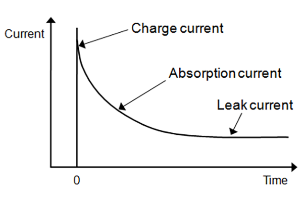
Current I(t) flowing after time t passes are categorized into three types as seen in the equation (1) below, namely, charge current Ic(t), absorption current Ia(t) and leakage current Ir.
I(t) = Ic(t) + Ia(t) + Ir ...... equation (1)
Charge current indicates current flowing through an ideal capacitor. Absorption current flows with a delay compared with the charge current, accompanying dielectric loss at a low frequency and the reverse polarization for high dielectric constant type capacitors (ferroelectric) and the Schottky barrier which occurs at the interface between the ceramics and the metal electrodes.
Leakage current is a constant current flowing after a certain period of time when the influence of absorption current diminishes.
Therefore, the value of the flowing current varies depending on the amount of time voltage is applied to the capacitor. This means that the capacitor's insulation resistance value cannot be determined unless the timing of the measurement after voltage application is specified.
The insulation resistance of a multilayer ceramic capacitor represents the ratio between the applied voltage and the leakage current after a set time (ex. 60 seconds) while applying DC voltage without ripple between the capacitor terminals.
It is difficult to clearly distinguish among charge current, absorption current, and leakage current.
Specification and units of insulation resistance
As described above, the unit of insulation resistance is expressed as resistance [MΩ] or [Ω・F] or CR product [MΩ・μF].
The CR product [MΩ・μF] is the product of the nominal capacitance value and the insulation resistance value.
Unit depends on the part number.
Please check the Detailed Specification Sheet for each part number.
Method for calculating insulation resistance [MΩ] from CR product [MΩ・F]
Example: When the CR product is 500 Ω・F or more and the capacitance is 1 μF
-> 500 ΩF / 1 μF = 500 MΩ or more
As shown above, the higher capacitance value, the less its insulation resistance becomes. The reason is explained below.
Insulation resistance can be figured out with the Ohm's law from applied voltage considering the multilayer ceramic capacitor as a conductor as well as electric current.
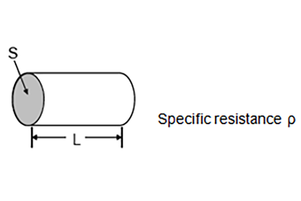
Resistance value R may be expressed with equation (2) with the length of the conductor as L, and the area of cross section as S and specific resistance as ρ.
R = ρ・L/S ...... equation (2)
Likewise, capacitance C can be represented with equation (3) by expressing distance between electrodes for the multilayer ceramic capacitor (dielectric thickness) as L, the area of inner electrode as S and the dielectric constant as ε.
C ∝ ε・S/L ...... equation (3)
Equation (4) can be derived from equation (2) and equation (3) indicating that R and C are inversely proportional.
R ∝ ρ・ε/C ...... equation (4)
Insulation resistance being higher indicates that the leakage current under DC voltage is lower. Generally, circuits are supposed to have higher performance when the insulation resistance value is higher.
Reference FAQ
What precautions for insulation resistance must be observed when using capacitors?
What are the leakage current specification values for DC?
What is the units of insulation resistance for ceramic capacitors?