
Increasing Communication Speeds - The Basics of Digital Communication
In a previous article, "Digital Modulation - The Basics of Digital Communication," we explained digital modulation where 1 bit of data represented as "0" or "1" is transmitted by assigning it to two states of the modulated wave as follows:
• ASK: based on the size of the amplitude
• FSK: based on two frequencies
• PSK: based on two phases
These can be considered the starting point of digital modulation, and are also called binary digital modulation. In fact, much of the digital modulation employed by communication devices around the world is multivalue digital modulation, which realizes higher communication speeds (i.e., more efficient data transmission) than binary digital modulation. This article will explain multivalue digital modulation.
(There is also the method of expanding the frequency bandwidth to increase the communication speed, but this will be covered in a separate article.)
1. QPSK Modulation: The Basics of Multivalue Digital Modulation
For example, based on the PSK approach described in the previous article, "Digital Modulation - The Basics of Digital Communication," when comparing a BPSK*1 modulated wave where the phase changes between the two states of 0° and 180° and the case with that modulated wave multivaluated to QPSK*2 that has the four states of 45°, 135°, 225°, and 315°, the QPSK modulated wave is able to send 2 bits of data at a time: "00," "01," "10," and "11" (Fig. 1). Assuming the same symbol length*3 for both BPSK and QPSK, this shows that multivaluation can increase the communication speed.
*1 BPSK: Abbreviation of Binary Phase Shift Keying
*2 QPSK: Abbreviation of Quadrature Phase Shift Keying
*3 In binary digital modulation such as ASK, PSK, and FSK, 1 symbol expresses 1 bit, and in this case, the symbol length is often referred to as the bit length.

2. QAM: Typical Multivalue Digital Modulation
In the QPSK modulated wave in the previous section, only the phase changes, but by adding high/low variations in amplitude to create an 8-state modulated wave, it is possible to transmit 3 bits of data at a time: "000," "001," "010," "011," "100," "101," "110," and "111" (Fig. 2). This results in even higher speeds compared to the QPSK modulation in Fig. 1.

[Supplement]
Fig. 3 shows an example of a modulator configuration for generating a QPSK modulated wave in order of steps (1) to (3) below. In multivalue digital modulation, series/parallel conversion of the signal is required.
(1) The bit sequence of the binary baseband signal (the moving original data) is divided alternately into 1-bit segments by serial/parallel conversion.
(2) Modulated waves are generated by multiplying each bit with carrier waves that have a phase difference of 90°.
(3) The two modulated waves are combined.
Note that QPSK is a modulation method with a constant amplitude, so it is also referred to as 4QAM.

3. Communication Devices that Employ QAM
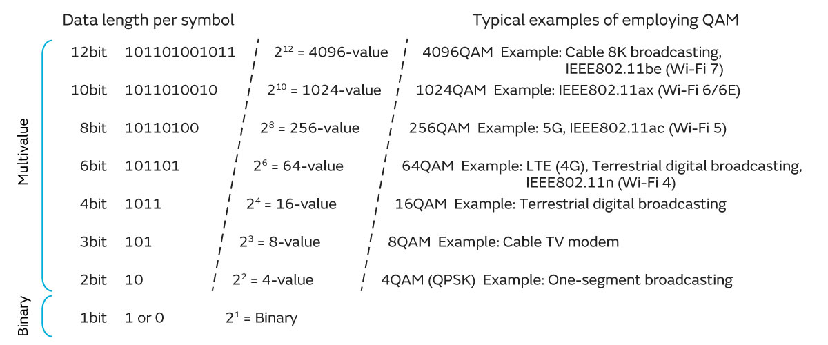
4QAM shown in Fig. 3 represents 2 bits (4 values) with 1 symbol. Furthermore, there are also modulation methods that allow for even greater multivaluation, such as 3 bits (8 values) with 8QAM and 4 bits (16 values) with 16QAM. Multivalue QAM has already been put to practical use, with 1024QAM adopted in Wi-Fi 6/6E (IEEE 802.11ax) and 4096QAM adopted in Wi-Fi 7 (IEEE802.11be) (Fig. 4).
Column: What Is Modulation Speed?
The previous article, "Digital Modulation - The Basics of Digital Communication," indicated that modulation speed*4 is a type of data speed (Table 1). This column explains modulation speed.
| Data speed | Unit | |
|---|---|---|
| Communication speed (Transmission speed) | Signal speed | bps (also bit/s, b/s) |
| Transfer speed | B/s (also byte/s, Byte/s), bps (also bit/s, b/s) | |
| Modulation speed | baud | |
*4 This is also referred to as the symbol rate.
The modulation speed is the number of symbols shown in Fig. 1 and Fig. 2 that can be transmitted per second, so it can be calculated as "1/symbol length." The modulation speed can be considered the data speed used in multivalue digital modulation.
(To reiterate, in multivalue digital modulation, a single symbol represents multiple bits as shown in Fig. 4. This is 2 bits for QPSK and 6 bits for 64QAM, etc.)
Incidentally, the modulation speed in baud units and the signal speed in bps units have the following relationship:
Signal speed = Modulation speed × Number of states that can be represented by modulation
For example, if the modulation speed of 64QAM (the number of states that can be represented by modulation is 6 bits) is 1200 baud, the signal speed is as follows.
Signal speed = 1200 baud × 6 bits = 7200 bps
Note that while a faster modulation speed enables transmission of more data, it may also become more susceptible to electromagnetic noise from the external environment (transmission data errors may increase).
Column: What Is a Carrier Wave and How Is It Used in Analog Modulation (AM/FM)?
This article used the term "carrier wave" when explaining digital modulation. Now, let's take a look at the mechanism of modulation centering on this carrier wave.
If we were to define a carrier wave, it would be as follows.
"In electrical communications, whether wireless or wired, it refers to a continuous wave (sine wave) or pulse wave that plays the role to transmit analog audio data and digital data such as text, audio, and images over long distances." (Here, a continuous wave is treated as a carrier wave*5.)
When attempting to deliver some data over a distance such as several kilometers, the baseband signal itself, which is the movement of data, has a short communication range, so it cannot be delivered that far. Therefore, an operation called modulation is performed by the transmitter to deliver the data over a distance. Modulation here refers to the process of imposing the baseband signal on a continuous wave carrier wave with a single frequency that is higher than the frequency components of the data. (Speaking precisely, the carrier wave is modulated by the baseband signal to generate a modulated wave.) This modulated wave is then transmitted as a radio wave from an antenna, enabling long-distance transmission (Fig. 5).
*5 "Carrier wave" is used the sense that it is a bearer of data. It is also sometimes referred to simply as "carrier."

The above explanation and image are for a carrier wave in digital modulation, but they apply similarly to analog modulation.
Typical examples of analog modulation are AM and FM. You may have heard the terms AM and FM radio broadcasting.
AM stands for Amplitude Modulation, and is a modulation method that changes the amplitude of a carrier wave according to the amplitude of the signal wave of the audio to be sent (Fig. 6a). Fig. 6a shows that in an AM modulated wave, the amplitude of the carrier wave fluctuates according to the amplitude of the signal wave.
In addition to this time axis characteristic, when looking at the AM frequency components (spectrum) on the frequency axis (Fig. 6b), there is the characteristic that the spectrum appears at fc+fs and fc−fs, where fc is the frequency of the carrier wave, and fs is the single frequency of the signal wave.
Due to these characteristics, AM is prone to frequency fluctuations due to the effect of interference from environmental noise, particularly electromagnetic noise, and due to multipath reflection of radio waves. Thus, while the frequency bandwidth for audio is narrow, making it advantageous for multiplexing, it can be considered a modulation method with significant concerns about degradation of communication quality.
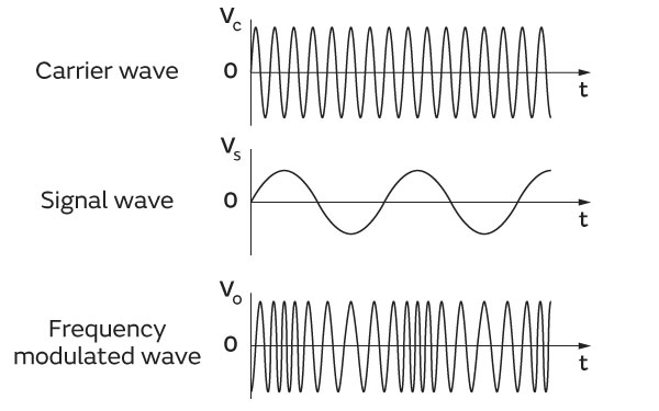
Next, FM stands for Frequency Modulation. Like AM, the audio signal is imposed on the carrier wave, but this modulation method changes the phase of the carrier wave according to the amplitude of the signal wave of the audio to be sent (Fig. 7a). As shown in Fig. 7a, this phase change results in a high frequency where the voltage of the signal wave is high, and a low frequency where the voltage is low. The waveform of an FM modulated wave has a constant amplitude that does not change as in AM modulation, but states with differing density due to changes in frequency can be seen. This density represents the amplitude of the signal.
Additionally, looking at the FM spectrum on the frequency axis (Fig. 7b), there is the characteristic that when the signal wave is the single frequency fs, the spectrum spreads in the manner of fc±nfs (where n is an integer) around the carrier wave frequency fc.
Due to these characteristics, unlike AM, FM is resistant to noise and multipath reflection of radio waves, and while it is not suitable for multiplexing, it can be considered a modulation method capable of maintaining high communication quality.


*6 Envelope: The line that shows the outline in the signal waveform and spectrum. In Fig. 6a, the wavelength of the envelope of the amplitude modulated wave is the same as the wavelength of the signal wave.