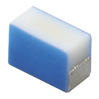
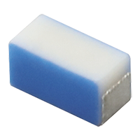
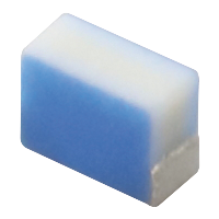
LQP03HQ series

Noise suppression technologies/case study introduction (Consumer)
INDEX
Some 5G communication services have been launched and are expected to usher in a new era of next-generation communication. On the other hand, because this communication is found in environments with LTE, Wi-Fi, and other existing communication systems, more complex noise issues are foreseen. Before 5G devices fully enter communication environments, we studied the noise environments for 5G communication and examined the noise suppression measures that will be needed.
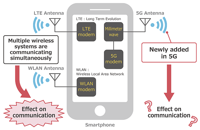
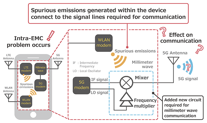
5G communication environments are expected to be used alone in few actual cases. Instead, typically, they are expected to be added to existing communication environments. In these environments, the spurious emissions generated inside devices due to existing wireless communication can connect to 5G wireless circuits and result in communication interference.
We are finally at a state where actual 5G devices have started to appear, but because it takes time to evaluate using actual devices, we envisioned a system where a millimeter wave circuit like that shown in the figure was added to a 5G communication circuit. We then used frequency multiplier and mixer test boards installed in the circuit to evaluate the effect when external noise connects to a signal line required for operation. In this study, spurious emissions are defined as excess signals other than the communication signals themselves, and they include communication signals from other communication and high-order harmonics.
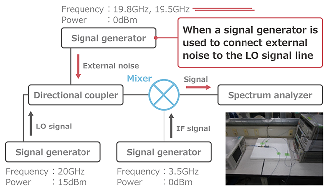
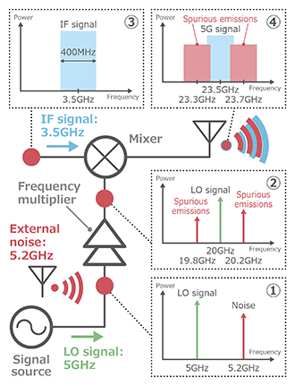
In order to discern the circumstances of millimeter-wave circuits coupled with external noise, this phenomenon was evaluated using the evaluation system shown in the following figure. External noise is coupled with the directional coupler in the LO direction of the substrate, in which the mixer is used to couple the LO and IF signals. 20 GHz frequency/15 dBm power is entered into the LO signal line and 3.5 GHz frequency/0 dBm power into the IF signal line. External noise with a frequency similar to that of the LO signal at 19.8 GHz and 19.5 GHz frequency is entered at 0 dBm power.
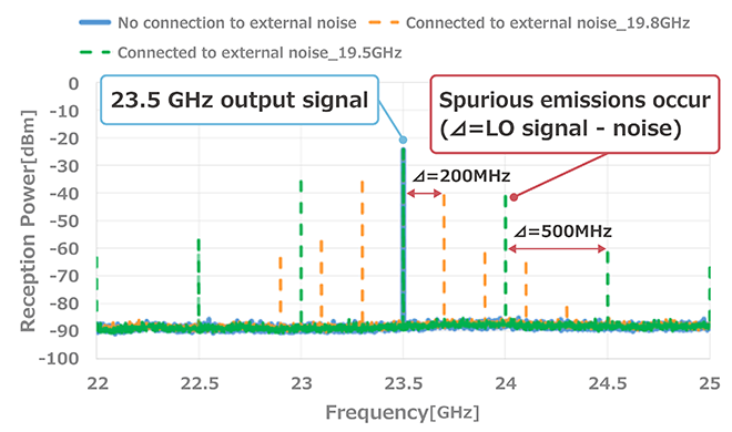
On the other hand, when external noises at 19.5 GHz and 19.8 GHz were connected, we found that, in addition to the expected 23.5 GHz output from the mixer, spurious emissions for the difference between the LO signal frequency and noise frequency were generated.
In the same way, the generation of spurious emissions was also confirmed in the frequency multiplier.
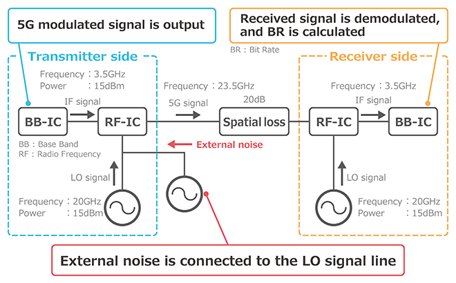
To evaluate whether these spurious emissions actually affect communication, we verified using the communication simulator SystemVue® by Keysight.
The simulations using SystemVue® use simplifications of the actual model as shown below.
A modulated signal for the 5G communication system is output from the BB-IC of the transmitter side, and this is combined with the LO signal in the transmitter-side RF-IC to up-convert to a millimeter wave frequency, and the 5G communication signal is output.
The transmitted signal is combined with the LO signal in the receiver-side RF-IC and down-converted, and signal demodulation in the BB-IC is performed, and the BR (Bit Rate) is calculated.
External noise was connected to the LO signal line in this evaluation system, and its effect was evaluated.
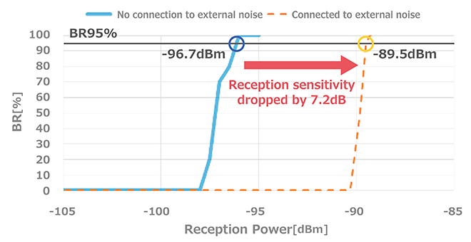
The reception sensitivities before and after connecting the noise were compared. The reception sensitivity before noise connection was -96.7dBm, and the reception sensitivity after noise connection was -89.5dBm, indicating a drop in reception sensitivity of 7.2dB.
In this study, the reception power at a BR of 95% was defined as the reception sensitivity. Consequently, this showed that connecting noise to the LO signal line in the mixer and frequency multiplier adversely affected communication.
We summarized the mechanisms where interference occurred due to noise. Noise connected to the LO signal line enters the frequency multiplier, and spurious emissions are generated. These spurious emissions are combined with IF signals at the mixer, and the 5G signals and frequency band are superimposed. As a result, incorrect signals are transmitted from the antenna, and a communication error occurs at the receiver side.
For this reason, measures for preventing entry of noise to the LO signal line are needed for preventing noise interference.
■Noise Interference Generating Mechanism
【Result】
Incorrect signals are transmitted by the antenna, and a communication error occurs at the receiver side.
From previous studies, we found that noise could be suppressed by preventing the inflow of noise to the LO signal line.
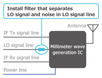
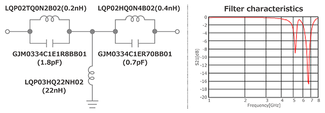
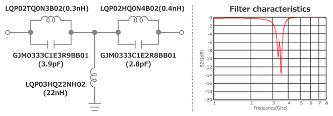
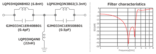
Specifically, in this method, a filter for removing the noise frequency band is installed in the LO signal input line of the IC that generates the millimeter wave. The filter combines an inductor and capacitor, and these elements must be set based on the target noise frequency.
Case for LO signal frequency of 5 GHz and inflow of noise as 5.2 GHz band WLAN signals
Case for LO signal frequency of 3.1 GHz and inflow of noise as 3.3 GHz Sub-6 signals
Case for LO signal frequency of 4.4 GHz and inflow of noise as 4.2 GHz Sub-6 signals
In 5G wireless circuits, the inflow of high-frequency signals to the LO signal line generates spurious emissions in the frequency multiplier and mixer, which can reduce signal quality and lead to a communication error.
To suppress this noise, a filter that prevents the inflow of noise to the LO signal line must be installed. The appropriate constant must be selected for this filter by taking into account the LO signal frequency and noise frequency.

