Capacitor
PRODUCT FOCUS
AEI by Dempa Publications, Inc., Dec 2016
Murata Manufacturing Co., Ltd. has developed a dynamic model of multilayer ceramic capacitors and has publicized it on its website (Figure 1). The dynamic model allows circuit simulations to reflect properties resulting from the application of a specified temperature and DC bias voltage. This article provides an overview of the dynamic model and an example of its application to circuit simulations.
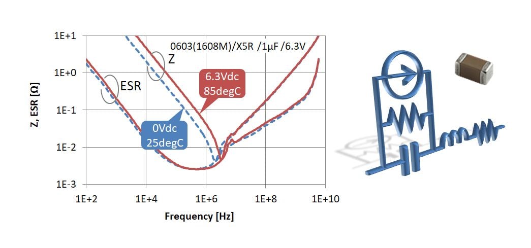
In recent years, designing electronic devices has become more difficult, as the speed of signals and the number and density of mounted components have increased. Designers need to create a high-accuracy design within a short-time period by reducing the number of prototyping experiments and by using circuit simulations in order to reduce prototyping costs. Carrying out high-accuracy simulations requires high-accuracy component model settings. Multilayer ceramic capacitors, particularly those with high permittivity, have dependence on temperature and DC bias voltage, and fluctuations in their capacitance or equivalent series resistance (ESR) become considerable depending on conditions. For example, when designing a DC/DC converter, it is necessary to consider dependence on temperatures due to heat generation, in addition to dependence on DC bias voltage (Figure 2). In such a situation for design, there has been a demand for component models that can dynamically reflect dependence resulting from the operating conditions for circuitry.
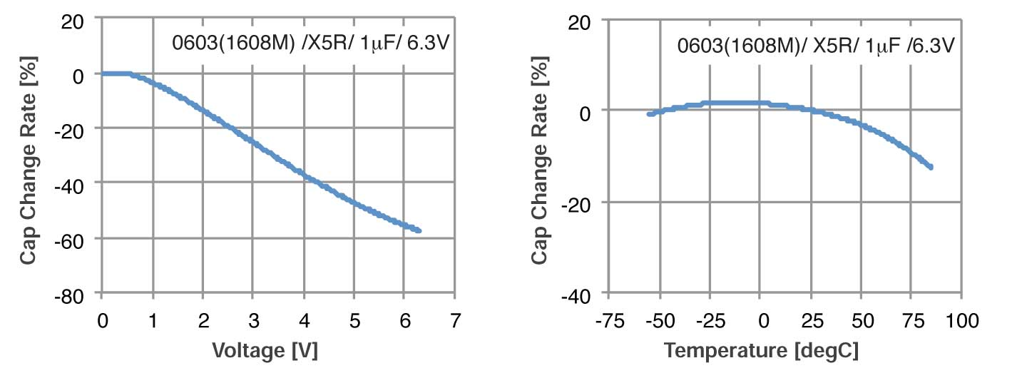
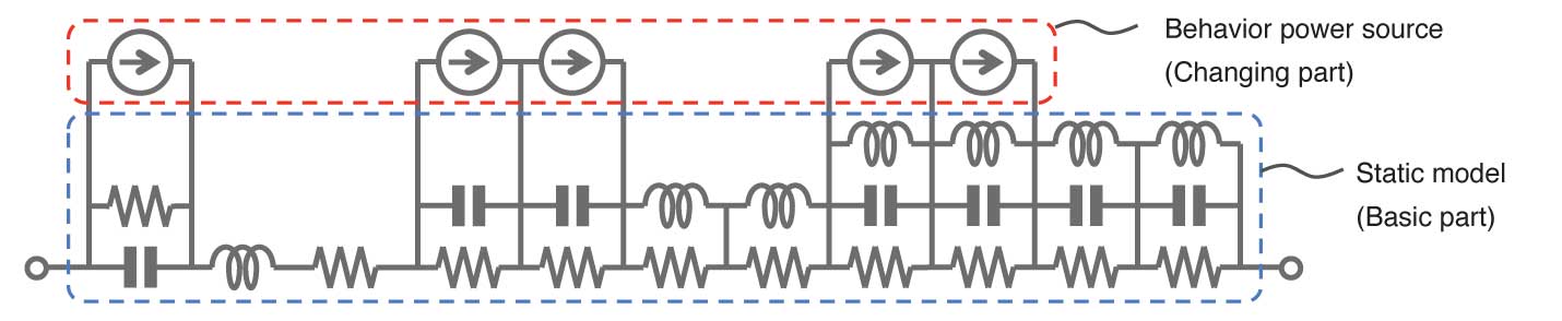
The dynamic model of multilayer ceramic capacitors (component model for simulation that can dynamically reflect the factors for differences in properties) that Murata offers allows a circuit simulation to highly accurately and dynamically reflect properties resulting from application of a temperature and a DC bias voltage. It is based on an equivalent circuit model, which is a static model [Component model for use under specified conditions. Consists only of basic circuit elements (R, L, C)] where the DC bias is 0V at a normal temperature (25°C), and has a current source model referred to as a behavior power source, which is connected in parallel to this equivalent circuit model. The current source model automatically calculates changes in capacitance and ESR that result from application of a temperature and a DC bias voltage, and this serves as a mechanism to dynamically reflect dependence on temperature and DC bias voltage (Figure 3).
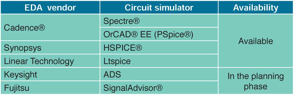
The elements that constitute the dynamic model are basic and compatible with various types of analysis, such as DC analysis, AC analysis and transient analysis, and so allow efficient, high-accuracy circuit design. Table 1 shows the availability of Murata’s dynamic model for each circuit simulator. The model library compatible with each of the software programs, which has been used by many users, who gave favorable reviews, can be downloaded from the company’s website (https://www.murata.com/).
Design support software SimSurfing, which is also availableon the website (https://ds.murata.com/simsurfing/index.html?lcid=en-us), allows users to graphically check various properties that are calculated using the dynamic model. For example, it makes it easy to compare impedance-frequency characteristics, changing the DC bias voltage of more than one component. Also, by entering a temperature and a DC bias voltage on SimSurfing, Sparameters and a SPICE netlist can be output under the input conditions. The output SPICE netlist is a static model consisting only of basic circuit elements (R, L, C), and so is effective in using a simulator incompatible with the dynamic model or in reducing calculation loads. Note that although a static model cannot automatically respond to freely set conditions on a circuit, it is precisely identical to the dynamic model under uniquely specified conditions.
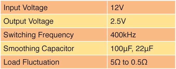
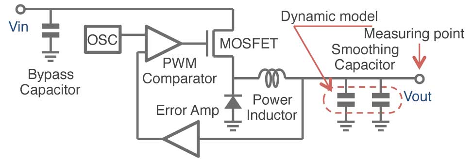
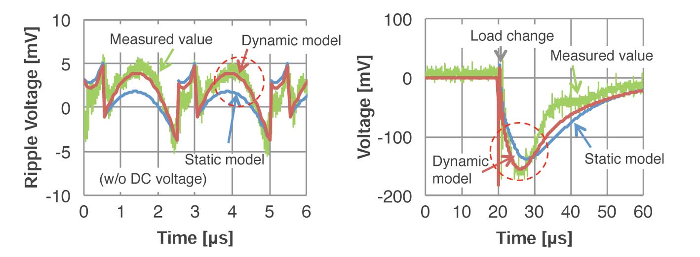
This section gives an example of application of the dynamic model to characteristic analysis of a DC/DC converter. Figure 4 shows a circuit diagram of a step-down DC/DC converter, with which voltages measured at the output terminal were compared with simulated values. The dynamic model was applied to the smoothing capacitor of the output circuit, and for comparison, calculation results were obtained including those from cases where a conventional static model (temperature: normal; DC voltage: 0V) was used. Table 2 gives details of the measurement and calculation conditions. Figure 5 illustrates ripple voltage at the output terminal (left) and voltage transient response resulting from a load change (right). The figure, where the DC component of ripple voltage was removed for comparison, shows that the dynamic model provided closer approximation. As for transient response, also, the figure shows voltage waveforms given when the load changed from 5 to 0.5Ω (the current changed from 0.5 to 5A). Immediately after the load change, the level of the output voltage decreased steeply, but the calculation results from the dynamic model were very nearly identical to the measured values. In the steadily rising part of the voltage, which is a section affected by the characteristics of the power inductor in association with increases in the direct current, there was slight difference because the dynamic model was not applied to the power inductor in this example.
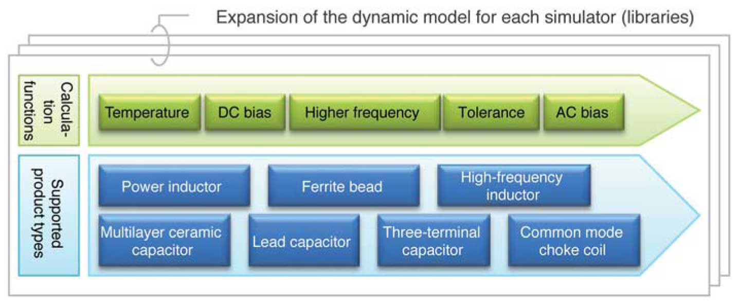
The methods that Murata used to create a dynamic model are highly versatile, and so are easy to apply to other products. While a power inductor has DC superposition characteristics that depend on the physical properties of the materials, the company’s dynamic model can reflect the dependence of the inductance and the Q factor on direct current. Therefore, the combination of its dynamic model and multilayer ceramic capacitors allows more accurate simulations. Murata will offer libraries of its dynamic model for many simulators while adding new calculation functions and expanding the range of product models that it supports, in order to respond to users’ various requirements (Figure 6).
This article describes a dynamic model of multilayer ceramic capacitors, along with an example of its application to circuit simulation. In development and design of products, requirements for product quality, such as signal integrity (SI), power integrity (PI), and electromagnetic interference (EMI), are becoming much stricter, and provision of high-accuracy models that reflect important properties of components are becoming increasingly important. Murata’s dynamic models are to respond to these demands, and it will expand their functionality and the range of product types that they support, in order to contribute to advancement in development and design that use circuit simulations.
About This Article:
Seiji Hidaka, CAD/CAE Technology Dept., Fundamental Technology Center, Technology & Business Development Unit, Murata Manufacturing Co., Ltd.