Noise Suppression Products / EMI Suppression Filters / ESD Protection Devices
Noise Suppression Filter Guide
Murata has assembled an extensive lineup of common mode choke coils, and offers many choices of common mode choke coils for signal lines depending on the required characteristics and size. In this article, we explain how to choose the best common mode choke coil in terms of characteristics.
We have discontinued the production of some of the products (DLP0QSA150HL2) introduced in this article.
Before going into the characteristics of common mode choke coils, we will first introduce the concepts of common mode signals and differential mode signals.
These concepts have already been introduced in "Basics of Noise Countermeasures [Lesson 6] Common mode choke coils",」but we will re-introduce them here using the example of differential transmission to transmit data through two signal lines.
As noted in the article "Why is differential transmission used for high-speed transmission?", differential transmission is the method used for high-speed data transmission. Examples of differential transmission methods include MIPI®, which is used for smartphone components such as cameras and displays, as well as HDMI®, DisplayPort, and USB for personal computers.
As shown in Figure 1, differential transmission uses two signal lines to flow opposite-phase currents, with the phases representing differences in the voltage and current waveforms.
This signal, called the differential mode signal, is used for the transmission of data (the differential mode is sometimes called the normal mode). Meanwhile, there is also a so-called "common mode" signal, which refers to the signal flowing in phase through the two lines. The common mode signal is unwanted from the perspective of differential transmission.
In other words, it is a form of noise, called "common-mode noise".
In actual high-speed differential transmission signals, the common-mode noise is mingled with the differential signal as shown in Figure 1. When you take the difference between the signals flowing through a pair of lines, the differential mode signals intensify each other, while the common-mode noise is canceled out. In this way, the differential transmission method is less susceptible to the impact of common-mode noise.
On the other hand, when observed from a distance, the signals emitted from differential transmission appear to overlap, as shown in Figure 2. In this case, the differential mode signals appear to cancel each other out, and the common-mode noises appear to strengthen each other. In other words, from a distance, differential transmission becomes more vulnerable to the impact of common-mode noise.
In cases where this type of noise is a problem, incorporating a common mode choke coil in the differential transmission lines is an effective way to remove common-mode noise.
The common mode choke coil is inserted across the paired differential transmission lines as shown in Figure 3. While the differential mode signal required for data transmission passes through the inserted common mode choke coil, the signal is attenuated to prevent passage of the common-mode noise.
In reality, the differential mode signal too is somewhat attenuated by the common mode choke coil. The amount of attenuation of both the differential mode signal and the common-mode noise signal depends on the frequency. These characteristics of the common mode choke coil are represented as differential mode insertion loss Sdd21 and common mode insertion loss Scc21. (Sdd21 and Scc21 are among the mixed-mode 4-port S parameters.)
Figure 4 shows the frequency characteristics of differential mode insertion loss Sdd21, and Figure 5 shows the frequency characteristics of common mode insertion loss Scc21. In Figures 4 and 5, the deeper graph line means the larger insertion loss. Figure 4 shows that the differential mode signal becomes more attenuated as the frequency rises. On the other hand, Figure 5 shows that the common mode insertion loss Scc21 follows a curve with a peak, indicating that the effectiveness of common-mode noise removal varies depending on the frequency.
The differential transmission signal frequency varies depending on the method of each interface, and the common mode choke coils that can be applied also vary accordingly.
Whether a common mode choke coil can be applied can be determined by looking at the transmission signal waveform.
From a broad perspective, the guideline that may be used is that the cutoff frequency of the common mode choke coil must be at least 3 times the signal frequency of the differential transmission standard. The cutoff frequency is the frequency at which the differential mode insertion loss reaches 3 dB. However, the "at least 3 times" guideline is only for reference, and there are often no problems with the signal waveform when the cutoff frequency is less than 3 times the signal frequency. (Since signal quality criteria such as eye pattern measurements are established at each interface, the suitability is ultimately determined against these criteria.)
On the other hand, problematic noise and its frequency vary depending on the electronic device, and the appropriate common mode insertion loss frequency characteristics also vary accordingly.
For example, if noise is generated that exceeds the limits prescribed in regulations on unwanted emissions, it is valid to choose a product with a large common mode insertion loss in the frequency band of the noise.
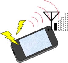
Common-mode noise emitted from a differential transmission may also worsen the device’s performance of personal wireless communications, including LTE and Wi-Fi (Figure 6). This can occur when the common-mode noise is emitted at the same frequency as the wireless communication and is received by the antenna. This is referred to as reception sensitivity suppression. In this case too, you can suppress the emission of common-mode noise and improve reception sensitivity by inserting a common mode choke coil.
We have discontinued the production of DLP0QSA150HL2.
As an example, we will explain how to choose a common mode choke coil in a case in which noise emitted from the MIPI® line of a display is suppressing reception sensitivity in the LTE band, which is the band from 700 MHz to 900 MHz.
We will assume that the MIPI® signal frequency is 500MHz. In this example, we will consider which of two types of common mode choke coil, whose characteristics are shown in Figure 7 and Figure 8, is better suited to the task: type A (DLP0QSA150HL2) or type B (NFP0QSN112HL2).
First, look at the differential mode insertion loss in Figure 7. Three times the signal frequency 500 MHz is 1.5 GHz. Since the cutoff frequencies of both common mode choke coils are above 1.5 GHz, they can be applied without problems. Next, if we examine the common mode insertion loss in the band from 700 MHz to 900 MHz in Figure 8, we see that common mode choke coil B (NFP0QSN112HL2) has the greater insertion loss.
In other words, common mode choke coil B (NFP0QSN112HL2) is more effective at reducing common-mode noise in the band from 700 MHz to 900 MHz and can be expected to better enhance LTE reception sensitivity.
(*Common mode choke coil A: DLP0QSA150HL2 vs. B: NFP0QSN112HL2)
For other case studies, see the examples of countermeasures against Wi-Fi reception sensitivity suppression described in the article "How to mitigate the deterioration in the reception sensitivity of WLANs using noise suppression methods?"
As described above, it is possible to choose a suitable common mode choke coil by identifying the differential transmission signal frequency and the frequency of the problematic noise, and then examining the differential mode insertion loss Sdd21 and the common mode insertion loss Scc21.
Murata can recommend a common mode choke coil for every differential transmission standard. When choosing a common mode choke coil, in addition to this article, be sure to refer to the lists of recommendations in the links below.
Click here for a list of recommendations for general applications
Click here for a list of recommendations for automotive use
Product Engineering Section 1, Product Engineering Department, EMI Filter Division
Murata Manufacturing Co., Ltd.
The information presented in this article was current as of the date of publication. Please note that it may differ from the latest information.