Energy-Saving Technology and Carbon Neutrality on High-Speed Railways
Railways are more energy-efficient than other modes of passenger transportation, with CO₂ emissions per ton-kilometer roughly one-seventh those of passenger cars. The difference is more pronounced over long distances, and high-speed railway networks contribute substantially to energy savings in transport infrastructure.
Although high-speed railway networks have long been part of the transport infrastructure of developed countries, developing countries have also moved toward constructing them in recent years. However, countries that have already put high-speed railway networks into practical use and have the corresponding technology are exploring public and private channels for marketing the infrastructure and technology to countries looking to establish networks. The infrastructure and technology must deliver high speeds, low noise, and safety as well as eco-friendly performance through reduced CO₂ emissions now that the focus includes achieving carbon neutrality.
Note: We will refer to electric trains as “rolling stock” for the rest of this article.
Eco-friendliness and electronics technology of rolling stock
Although railways are eco-friendlier than other modes of transport, they still consume a lot of electricity and fuel. Specifically, the worldwide proliferation of high-speed railway networks has increased CO₂ emissions, hampering efforts to achieving carbon neutrality. Therefore, further energy conservation is needed.
The key to improving the eco-friendliness of railways is energy-saving in drive systems. Three factors will contribute substantially to achieving this: energy-saving in actual drive systems, downsizing and reducing the weight of drive systems, and reducing the weight of rolling stock. Regarding the first two factors, developing converters and inverters with less power loss in drive systems is essential for reducing energy loads in rail transport and cutting CO₂ emissions. This development requires the adoption of high-performance semiconductor devices and low-loss capacitors and inverters.
Drive system power control technology
Of all the components of rolling stock, drive motors require the most power. To save energy in rolling stock, it is necessary to improve the efficiency of drive motors by limiting their electricity consumption. To achieve this, devices known as “inverters” are installed to efficiently control drive motors.
Inverter control
Presently, the power for most rolling stock is supplied via alternating current converted to direct current. The device that converts AC to DC is known as a “converter.” AC motors, air conditioning, lighting, and other equipment requiring AC power are equipped with inverters to convert DC to AC.
Inverters not only convert DC to AC, but can also control frequency and voltage, a capacity known as “inverter control.” Inverter control is widely utilized in air conditioners, microwave ovens, fluorescent lights, and other home electronics. The precision and efficiency of inverter control are major technological determinants of energy consumption in rolling stock, which requires large amounts of power.
Evolution of inverter control
Inverter control has been put to practical use on rolling stock since the 1980s. Originally, inverters worked using a method known as “pulse width modulation,” or PWM, in which output voltage is changed by converting DC voltage to block pulses through switching and varying the pulse width at regular intervals. Thyristors*1 were used in some of the main circuit elements, but later, gate turn-off (GTO) thyristors*2 became mainstream.
The mid-1990s saw the emergence of insulated-gate bipolar transistors (IGBTs),*3 which offer lower losses and higher-frequency switching than GTO thyristors and thus drove increases in efficiency and voltage control. Additionally, intelligent power modules (IPM), which integrate IGBTs with drive and protection circuits, have improved performance, functionality, and reliability, and have been put into practical use as a technology to advance inverters.
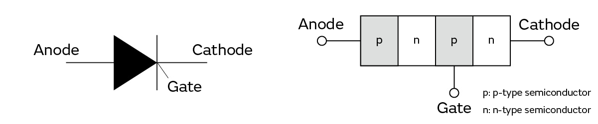
*1 A type of semiconductor device that performs switching operations (Figure 1). Thyristors are characterized by switching from a non-conductive state (Off) to a conductive state (On) between anodes and cathodes by applying voltage between gates and cathodes to allow currents to flow. These are known as “turn-ons” (ignitions). Notably, to cause switches to operate, a separate element or circuit is required to turn switches off (initiate a turn-off/extinguish) from the conductive state (On).
*2 Thyristors capable of turn-offs—which ordinary thyristors (See *1 above) could not do—and thus requiring separate gate circuits. However, disadvantages include slow turn-off times and large power losses because the current flowing through the gates can be 10% or more of the output current.
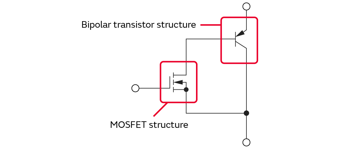
*3 Semiconductor devices compatible with large amounts of power, with a MOSFET structure for the input and a bipolar transistor structure for the output (Figure 2). IGBTs reduce loss with lower ratios of gate current to output current than GTO thyristors. Additionally, with a switching frequency outside the human audible range, noise levels are lower when IGBTs are used than when GTO thyristors are used.
Inverter control of drive motors in rolling stock
AC motors for rolling stock—electric motors that provide the driving force for trains—have become practical thanks to advances in power electronics technology, especially inverters. Using inverters results in substantial reductions in overall losses by providing better weight-to-output ratios than DC motors and eliminating losses from resistors employed in conventional rheostatic control. AC motors in use include synchronous motors and induction motors. Of the two, AC induction motors with variable voltage variable frequency (VVVF) inverter control systems*4 are widely used for their excellent durability and user-friendliness. Additionally, with the introduction of IGBT and IPM, which contribute to higher withstand voltages and larger power supply capacities, and the use of three-level inverter systems,*5 AC induction motors are becoming more economical, with less magnetic noise and fewer harmonics that cause electronic equipment to malfunction.
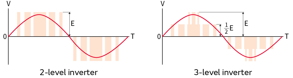
*4 Converts DC to AC using the same principle as PWM inverters, and also controls the rotation of AC motors by varying frequency and voltage. Under VVVF inverter control, voltage can be varied using high-speed, high-precision switching, and pseudo AC sine waves can be created by cyclically reversing the output direction (Figure 3).
*5 An inverter capable of outputting waveforms similar to sine waves. Significantly reduces switching losses compared to two-level inverter systems (Figure 3). Additionally, low-pass filters for converting output waveforms to sine waves can be downsized.
Required performance of electronic components of inverter control circuits
Presently, manufacturers are shifting from silicon (Si) to silicon carbide (SiC) and gallium nitride (GaN) as the materials for the semiconductor devices of inverters to achieve greater withstanding pressure and faster switching speeds. However, as switching speeds increase, the amount of heat generated also increases. Thus, the electronic components of each inverter circuit must also be highly heat-resistant.
Inverters comprise not only semiconductor devices, but also rectifier circuits; commutation circuits to operate thyristors; snubber circuits that suppress parasitic inductance, which causes ringing, and noise caused by surge voltage; and more. Capacitors, resistors, inductors, and other components are used in these circuits.
Low heat resistance of electronic components requires cooling equipment, and the lower the heat resistance of components, the larger and more complex the cooling equipment tends to be. Installing and expanding cooling equipment increases the weight of the rolling stock and causes excess electricity consumption.
Therefore, inverters must comprise heat-resistant electronic components to reduce rolling stock weight and electricity consumption. Inverters must also accommodate circuit board deflection, resist impulse voltage, and otherwise be reliable enough to function normally in demanding operating conditions.
Energy-saving technology and carbon neutrality on high-speed railways
Amid the ongoing construction of high-speed railways around the world, controversy surrounds the immense expense of some, particularly the high-speed rail project linking Los Angeles and San Francisco in the state of California in the United States (scheduled to open in 2033), which is expected to cost roughly 77.3 billion dollars,*6 and the High Speed Two (HS2) project to connect major cities in the UK.
National governments are investing extensively in these projects because of the environmental benefits of rail transport over other modes of transport; the level of investment also illustrates how governments are looking to rail transport as a trump card for achieving carbon neutrality, which is considered to be difficult. The trend also applies to new railway networks in developing countries, where electronics technology will undoubtedly attract more and more attention for its ability to reduce CO₂ emissions through energy conservation.
*6 Source: Comparison of High-Speed Railway Investment in Japan and the USA (Japanese Ministry of Finance). The link leads to a page in Japanese.
Related articles
- The Vision for Next-Generation Manufacturing of Murata's Distributed Exhaust Circulation One-by-one VOC Removal System - Simultaneously Reducing Environmental Impact and Costs
- Scope 3 Category 4 Reduction Measures - Taking On the Challenge to Both Increase Environmental Value and Reduce Costs Through Logistics and Packaging
- The GHG Protocol: Scope 1, 2, and 3 GHG Emission Reductions Companies Must Reach to Achieve Carbon Neutrality