Capacitor
Capacitor Guide
This technical column describes the basic facts about capacitors.
This lesson describes the heat-generation characteristics of capacitors.
As electronic devices become smaller and lighter in weight, the component mounting density increases, with the result that heat dissipation performance decreases, causing the device temperature to rise easily. In particular, heat generation from the power output circuit elements greatly affects the temperature rise of devices. However, in applications (switching power supply smoothing, high-frequency power amplifier output coupling, etc.) where large currents also flow in capacitors, the power consumption due to the loss component of the capacitors can increase to the point that heat generation by the capacitors cannot be ignored. Therefore, the temperature rise of capacitors must be suppressed to the range that does not affect the capacitor reliability.
An ideal capacitor has only a capacitance component, but an actual capacitor also has an electrode resistance component, dielectric loss, and an electrode inductance component, and can be expressed by an equivalent circuit such as shown in Figure 1.
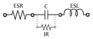
When AC current flows in this type of capacitor, the power consumption shown by Eq. 1-1 occurs due to the resistance component (ESR) of the capacitor, and the capacitor generates heat.

In order to measure the heat-generation characteristics of a capacitor, the capacitor temperature must be measured in the condition with heat dissipation from the surface due to convection and radiation and heat dissipation due to heat transfer via the jig minimized. In addition, when measuring a high dielectric constant-type capacitor with a nonlinear dielectric constant vs voltage, the AC current and AC voltage applied to the capacitor must be observed simultaneously. Furthermore, low-capacitance temperature-compensating-type capacitors require heat-generation characteristics at frequencies higher than 100 MHz, so measurement must be performed in the condition with little reflection.
Figure 2 shows a schematic of the system for measuring the heat-generation characteristics of high dielectric constant-type capacitors (DC to 1 MHz range).
The signal from the signal generator is amplified by a bipolar power supply and then applied to the capacitor. The current at that time is observed using the current probe, and the capacitor voltage is observed using the voltage probe. At the same time, the capacitor surface temperature is observed using an infrared thermometer to clarify the relationship between the current and voltage and the surface temperature.
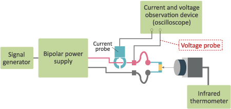
Figure 3 shows a schematic of the system and the measurement format for measuring the heat-generation characteristics of temperature-compensating-type capacitors (10 MHz to 4 GHz band).
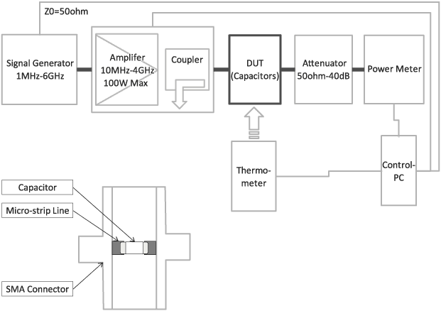
The devices and cables comprising this system are all standardized to 50 Ω, and the measurement sample is mounted on a board that forms a micro-strip line, with SMA connectors attached to both ends. The signal from the signal generator is amplified by a high-frequency amplifier, and applied to the sample (DUT) while observing the reflection with a directional coupler. The signal output via the sample is attenuated by a terminator (attenuator) and observed using a power meter. At the same time, the sample surface temperature is also observed.
Figure 4 shows the heat-generation characteristics data, impedance, and ESR frequency characteristics at 6.3 V for a 3216-type 10 uF with B characteristics, as an example of the heat-generation characteristics measurement data of a high dielectric constant-type multilayer ceramic capacitor.
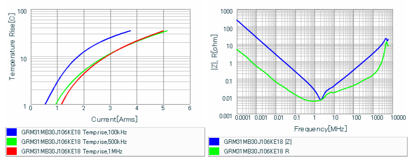
These graphs show the relationship between the AC current and temperature rise at 100 kHz, 500 kHz and 1 MHz, and the relationship between impedance (Z) and ESR (R) and the frequency. The heat-generation characteristics can be confirmed to become smaller in order of 100 kHz > 500 kHz > 1 MHz. In addition, the ESR is 10 mΩ at 100 kHz, 6 mΩ at 500 kHz, and 5 mΩ at 1 MHz, confirming that there is a deep relationship between ESR and the heat-generation characteristics.
Heat-generation characteristics data can be checked at the Murata website.
Figure 5 shows the window of the "SimSurfing" design assistance tool provided by Murata Manufacturing. Characteristics can be displayed by selecting the part number and the item to be checked. In addition, the SPICE net list and S2P data can be downloaded as simulation data. Please use this tool to help design various electronic circuits.
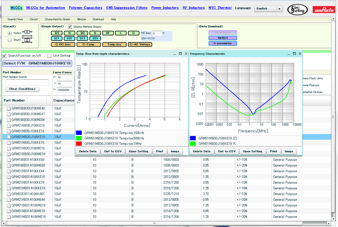
For more information on SimSurfing, visit the following URL:
https://ds.murata.com/simsurfing/index.html?lcid=en-us
Person in charge: S.K., Component Business Unit, Murata Manufacturing Co., Ltd.
The information presented in this article was current as of the date of publication. Please note that it may differ from the latest information.