PLT5BPH5013R1SN

Noise suppression technologies/case study introduction (Automotive)
INDEX
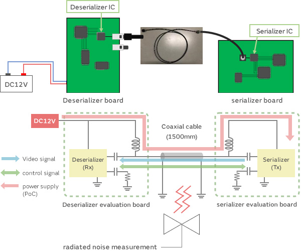
Next, we used SerDes evaluation boards with a PoC system to measure radiated noise and carried out noise suppression. We connected the Tx and Rx evaluation boards with a 1.5-meter automotive coaxial cable. We then supplied power on the Rx side and measured the radiated noise when the evaluation boards began operating.
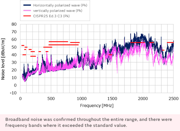
When we measured radiated noise, broadband noise was confirmed throughout the entire range from 30 MHz to 2.5 GHz, and there were frequency bands where it exceeded the standard value.
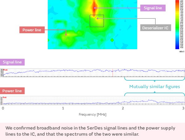
To check for noise sources on the board, we measured the near-field magnetic distribution on the board surface.
We monitored the wide-band noise spectrum of the SerDes signal lines and the power supply lines to the IC. In addition, we compared the spectrum shapes of both and found that the different values had similar figures.
This shows that the noise source for the signal lines is the same as that for the power lines.
Since the signal lines showed a higher level, we believe that the SerDes signals are the noise source.
*The DC-DC converter on this evaluation board does not use switching control, so switching noise is not the source of the magnetic field distribution.
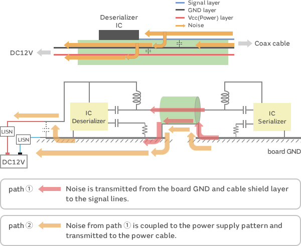
The assumed noise transition paths are as follows.
Path ①
Transmission of noise from board GND and cable shield layer to signal lines.
Path ②
Coupling of noise from path ① to power supply layer and transmission of noise to power cable.
Noise components in signals sent by the serializer IC are coupled with the GND layer on the board and transmitted along the coaxial cable in common mode (path ①).
These noise components are conveyed to the board mounted with the deserializer IC, coupled to the power supply layer in the board, and transmitted along the power cable in common mode (path ②).
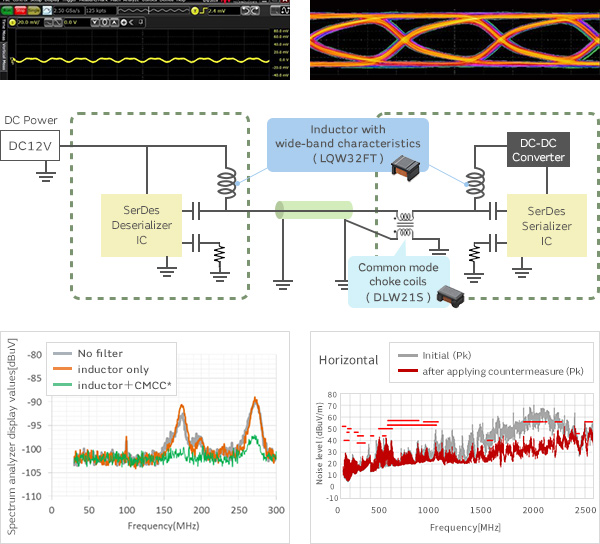
As a countermeasure for path ①, we installed a DLW21SH391XQ2 CMCC for the signal lines,
and as a countermeasure for path ②, we installed a PLT5BPH5013R1SN CMCC for the power lines.
As a result, noise was reduced by 10 to 20 dB in the range from 30 to 1,000 MHz, compared with not using a filter.
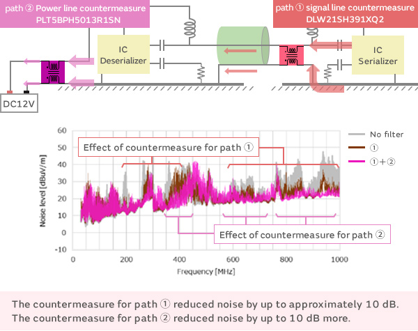
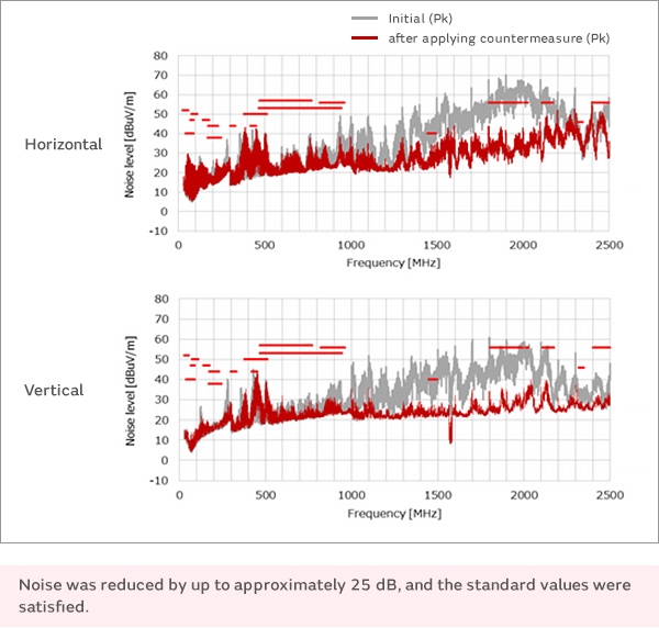
Applying both of the countermeasures together reduced noise by up to approximately 25 dB over the entire frequency range from 30 MHz to 2.5 GHz.