EMI Filters
During a DC fast charging session in an electric vehicle, the off-board charger delivers regulated power, while the vehicle determines how much voltage and current the battery can safely accept at each point in the charge cycle. This interaction depends on continuous communication between the charger and the vehicle.
The DC fast charging bypasses the vehicle's onboard charger. High-power AC/DC and regulated DC/DC conversion are performed in the off-board electric vehicle supply equipment (EVSE) that supplies DC directly to the vehicle's high-voltage traction battery path.
This coordination is becoming increasingly difficult as charging power increases. The vehicle has to then monitor cell voltage, battery pack voltage, current, temperature, isolation status, contactor state, and fault conditions while operating in a high-voltage, high-noise environment. If there is a loss of measurement accuracy, thermal visibility, communication integrity, or electromagnetic interference (EMI) robustness, the system may reduce charging current or interrupt the session.
DC fast charging performance therefore depends on the charger's rated power and the vehicle-side electronic components that monitor battery conditions and communicate with the charging infrastructure.
The execution of a DC fast charging session is a closed-loop control sequence in which the off-board charger regulates its output voltage and current based on limits specified by the vehicle.
In combined charging system-based DC fast charging, this relationship is governed by protocols such as ISO 15118 and DIN SPEC 70121. The digital communication stack uses Power Line Communication over the Control Pilot line that is running TCP/IP with IPv6. The handshake protocol progresses through multiple stages to establish and maintain a safe power delivery loop.
But the voltage and current limits of the battery change in real time depending on the temperature, state of charge (SOC), state of health (SOH), and individual cell voltages. The battery management system (BMS) has to recalculate the maximum allowable current to prevent overvoltage. If the communication is interrupted for any reason, the system is designed to reduce or stop power delivery to protect the vehicle and charging equipment.
During high-power DC charging, battery cells often operate closer to its voltage, temperature, and electrochemical constraints. The rate at which energy can be safely delivered into a Li-ion cell is determined by cell voltage, temperature, SOC, internal resistance, and the anode potential relative to the lithium metal.
If the BMS undervalues the true cell voltage or fails to detect temperature-dependent charging limits, it may allow excessive current or voltage stress. The BMS does not measure anode potential directly. It uses cell voltage, current, temperature, and SOC to avoid operating conditions associated with lithium plating. This degradation can reduce battery capacity and, in severe cases, increase the risk of internal short circuiting.
On the other hand, if the sensing system has poor accuracy or high noise, the BMS must build large safety margins into its control software. This forces the system to apply conservative charging curves, derating the charging current prematurely, and extending charging times.
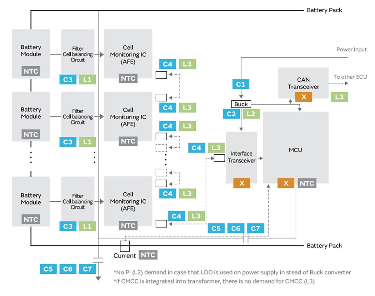
This shows that accurate measurement of cell voltage, pack voltage, pack current, and cell temperature has a direct influence on the trade-off between charging speed and safety margin. For example, many battery monitoring ICs specify cell voltage measurement accuracy in the low-millivolt range across automotive temperature conditions.
One major barrier to achieving this level of sensing precision is the electrically noisy high-voltage environment around the vehicle's high-voltage bus. The off-board charger's high-power switching converters, combined with active onboard systems such as auxiliary DC/DC converters, thermal-management drives, and low-voltage power supplies, introduce significant differential and common-mode noise into the battery packs. This noise couples directly into the cell monitoring wires.
The vehicle's auxiliary high-voltage to low-voltage DC/DC converter is not part of the main DC fast charging current path. But it may remain active to support low-voltage ECUs, cooling pumps, contactors, and the 12 V or 48 V electrical system. Specific 800 V class vehicles may also use an onboard boost function when connected to lower-voltage DC charging equipment.
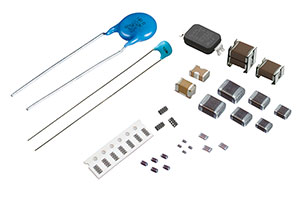
Without proper filtering, high-frequency noise can affect the input stage of the BMIC's ADC. This can cause aliasing, voltage offsets, or measurement drift. To address this, engineers use passive RC low-pass filters directly at the BMIC voltage-sensing inputs. For cell voltage monitoring lines, Murata offers the GCJ, GCM, and KCM Series of MLCCs to provide the capacitive element in RC low-pass filtering and decoupling networks around battery-monitoring IC inputs.
The rate at which energy can be safely delivered into a Li-ion cell is determined by cell voltage, temperature, SOC, internal resistance, and the anode potential relative to the lithium metal.
The sustained charging power of an EV is usually not limited by the maximum electrical capability of the off-board charger but constrained by the thermal limits of the vehicle-side components.
As charging currents increase, the resistive heating generated across the internal power path increases four times. This rapid heat generation occurs simultaneously across multiple subsystems, including battery cells, high-voltage connectors and charging inlets, main contactors and busbars, and power electronics.
If these electronic components reach their thermal limits, the vehicle may command a charging-current derating or stop the session. This prevents accelerated aging, contact degradation, connector overheating, insulation damage, and, in severe battery fault conditions, safety risks at the cell or pack level. Therefore, peak charging power is critical to the vehicle's ability to sustain high current before hitting thermal thresholds.
To maximize the duration of high-power charging, vehicle designers must use advanced thermal sensing and robust high-temperature-capable passive components. Murata lists NCU Series NTC thermistors to support continuous temperature measurement near cells, modules, and other thermally sensitive locations to allow the control system to monitor temperature and coordinate charging current derating.
Murata PRF Series PTC thermistors are suited to threshold-type overtemperature detection to provide an additional means to identify excessive temperature conditions.
In addition, the passive components integrated into the surrounding compact power electronics, such as capacitors, inductors, and EMI filters, must be rated for high-temperature operation. Passive components must be selected for temperature, ripple current, DC bias, mechanical stress, and lifetime requirements. Depending on component type, elevated temperature can change capacitance, increase losses, reduce current margin, or shorten operating life.
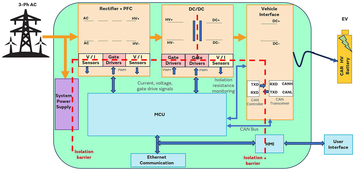
The high-voltage powertrain operates in a challenging electromagnetic environment. During DC fast charging, this environment is influenced by the off-board charger's switching stages, onboard auxiliary DC/DC converters, and high-voltage cabling. On the other hand, during AC charging, the onboard charger's PFC and isolated conversion stages add switching noise.
These switching harmonics, when combined with parasitic capacitances between high-voltage conductors and the vehicle chassis, create pathways for common-mode and differential-mode EMI. The interference can disturb low-voltage electronics, sensing circuits, communication links, and control loops.
The BMS cell-voltage and pack-current measurement can be distorted due to the high-frequency noise on the cell sensing lines that introduce offsets and ripples. The noise can also interfere with low-voltage control circuits, auxiliary DC/DC converter, and communication interfaces to affect the stability and reliability of vehicle-side electronics.
To achieve electromagnetic compatibility and comply with automotive standards (such as CISPR 25 and ISO 11452-4), designers need to implement a systematic filtering and noise-suppression at the component level.
In the off-board DC fast charger, common-mode filtering is required across high-voltage power conversion stages to control conducted and radiated noise. The common-mode chokes can be combined with rated capacitors between high-voltage nodes and protective chassis that are exposed to the relevant safety, leakage-current, and insulation requirements.
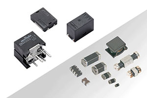
For low-voltage communication buses, chip-sized common-mode chokes, such as the Murata DLW32SH and DLW43SH series for CAN, can be placed near the physical transceiver ports to reject common-mode noise while allowing the differential communication signals to pass unimpeded.
Reliable support for 400 V and 800 V-class EVs therefore requires efficient active rectification, regulated DC/DC conversion, a low-inductance high-voltage DC link, safety-certified common-mode filtering, accurate output and isolation sensing, robust communication and coordinated thermal derating.
Murata's MLCC, safety-capacitor, EMI-suppression, timing-device and thermistor portfolios help designers reduce switching noise and loss, improve mechanical and thermal reliability, maintain communication integrity, and build compact, scalable chargers for current and next-generation EV platforms.