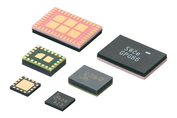
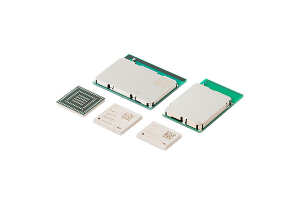
Connectivity Modules

Index: Wireless Mechanism (1)
1. What Is Wireless Communication?
2. Examples of Wireless Communication Applications
3. Basic Configuration and Elements of Wireless Communication Systems
4. Wireless Communication Method: Modulation and Demodulation
5. Data Transmission Direction: Duplex (Full Duplex and Half-duplex) and Simplex
6. What Is a Communication Protocol?
Column: History and Evolution of Wireless Communication
It is no exaggeration to say that modern society is supported by communication technologies such as mobile phones, Wi-Fi, radios, transportation IC cards, and television broadcasting. The communication we refer to here is communication using electricity—telecommunication. Telecommunication has undergone various technological innovations since its invention more than 250 years ago. It is even continuing to progress today especially with digitalization including 5G and IoT.
In this way, telecommunication has already become a part of our social infrastructure. Nevertheless, it is not easy to grasp an overall view of telecommunication due to its wide-ranging specifications and applications. For example, there are explanations of the technical aspects such as the signal form (digital and analog), the signal direction (duplex and simplex), and the transmission path (whether or not there is a cable), but it is rare to see comprehensive coverage of telecommunication-related content.
Accordingly, we wanted in this article to focus on wireless communication and to provide the basic materials to understand wireless communication together with the technical aspects while introducing our communication-related components and modules. This article is aimed at beginners who need wireless knowledge and those who have an interest in communication itself. We hope this article will be useful to those who want to broadly know and understand wireless communication knowledge.
Note: This article attempts to give an outline explanation of wireless communication. Accordingly, we have not fully explained some areas and left out other areas altogether. We plan to cover those areas little by little in the future.
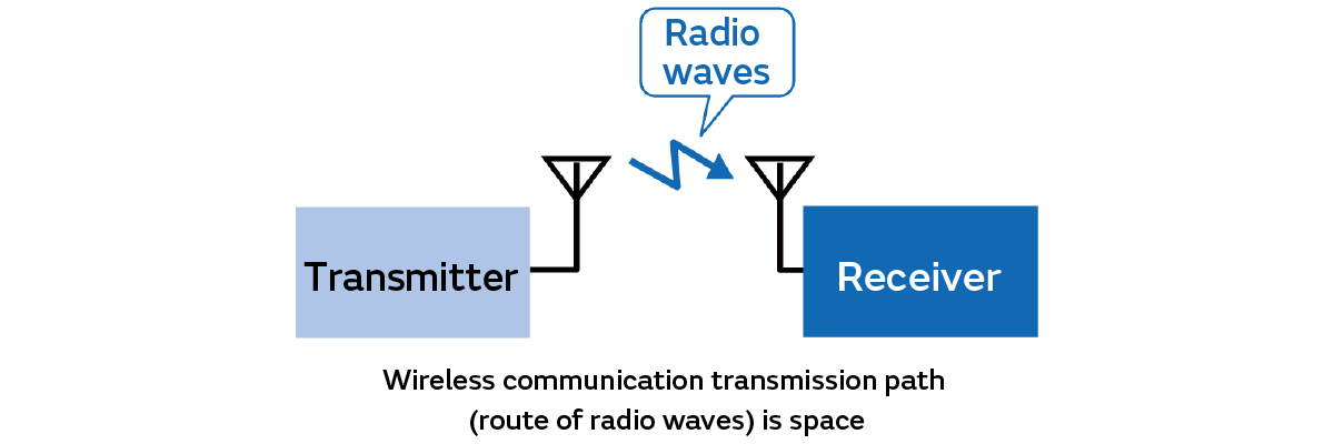
Put simply, wireless communication is wireless telecommunication that uses electromagnetic waves (radio waves), magnetic fields, and electric fields, whereas optical communication uses light without using wires or cables. Among the various methods of wireless communication, telecommunication that uses radio waves enables long-distance communication in the order of kilometers or more and allows lots of data (information)*1 to be transmitted. Therefore, radio waves are used in most wireless communication systems. We would like to focus our explanation mainly on radio waves in this series.
Wireless communication systems that use radio waves are configured to use space as the transmission path (or communication channel) and to send data on radio waves as signals*1 from transmitters to receivers (Fig. 1).
*1: We consider “data,” “information,” and “signals” here as follows.
・Data: A collection of symbols and codes that represent facts
・Information: Data including audio, text, and images that can be interpreted by humans and used in ways such as to determine things and take actions
・Signals: Data or information transmitted over time across transmission paths (communication channels) such as space or cables
We do not distinguish between “information” and “data” from here on for convenience. We use the expression of “data” unless otherwise specified.
Table 1 summarizes the approximate categories of wireless communication that transmit data using radio waves and the typical applications of each category. Wireless communication is used in various fields. The applications and types of wireless communication are also wide-ranging.
We should note here that wireless communication is also being developed beyond the boundaries of these categories in recent years. For example, various countries have begun satellite mobile communication services that incorporate satellite communication into mobile communication (smartphones equipped with a function to connect to satellites).
Categories of Wireless Communication | Typical Applications |
|---|---|
Mobile communication | Mobile phones |
Aviation communication | Radio altimeters, radars for air traffic control |
Satellite communication | Satellite broadcasting, GPS, weather observation |
Ship communication | LF beacons, MF/HF/VHF wireless communication |
Broadcast communication | AM/FM radio broadcasting (audio), television broadcasting (video) |
Fixed communication (microwave communication) | Long-distance telephone call relays, television relays |
Wireless network communication | Bluetooth®, UWB, Wi-Fi, Wi-MAX, LPWA, etc. |
Term | Description |
|---|---|
Global Positioning System (GPS) | A satellite positioning system for the entire earth. |
Low Frequency (LF) | Also called long wave. |
Medium Frequency (MF) | Also called medium wave. |
High Frequency (HF) | Also called short wave. |
Very High Frequency (VHF) | Also called ultra-short wave. |
Microwaves | Also described as Super Very High Frequency (SHF). |
Amplitude Modulation (AM) | A type of communication technology that |
Frequency Modulation (FM) | A type of audio communication technology similar to AM. |
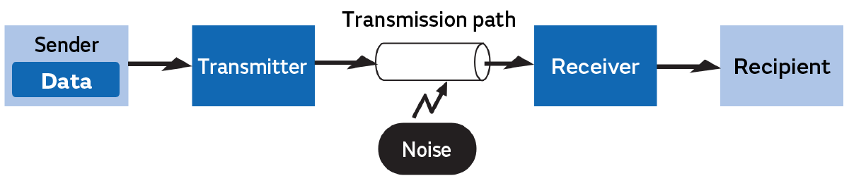
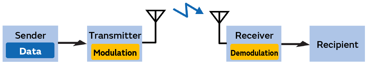
The basic model configuration of wireless communication systems (and wired communication systems) is as in Fig. 2. We describe its constituent elements in Table 2. Figure 1 in “1. What Is Wireless Communication?” is an even more simplified illustration of this basic model.
We call the data transmitted through a transmission path a “signal.” We refer to the unnecessary components that negatively affect these signals and make it difficult to transmit the data we want to send to the recipient “noise.” In practice, noise may occur in both transmitters and receivers and then cause interference with the operation of devices and other problems. In other words, we can call a communication system completely unaffected by this noise the ideal communication system.
Constituent Elements | Description |
|---|---|
Sender | The person sending data |
Data | Audio, text, still images, videos, etc. |
Transmitter | The device that converts the information you want to pass along |
Transmission path (communication channel) | The medium in which signals are transmitted from the transmitter |
Receiver | The device that converts the signals passed along the transmission |
Recipient | The person who received data |
Fig. 3 shows a configuration that describes the modulation and demodulation that are the basic functions of a wireless communication system. It is based on the basic model of the communication system in Fig. 2.
If you try to directly transmit data as radio waves, you will not be able to send it over long distances. For this and other reasons, wireless communication requires an operation called “modulation” that converts data into convenient signals in the transmitter to enable the transmission of data over long distances. On the other hand, an operation called “demodulation” that returns the modulated signals back to the original data is required in the receiver.
Table 3 summarizes the typical modulation technologies and adoption examples. Many of the terms are unfamiliar in general. However, we would like you to think of these modulation technologies as those that support part of our current lifestyle infrastructure such as mobile phones and radio and television broadcasts here. We plan to explain the details on a separate page at a later date.
Typical Modulation Technologies | Adoption Examples | |
|---|---|---|
Analog | ||
Amplitude modulation (AM) | Radio (medium-wave broadcasting, | |
Frequency modulation (FM) | Radio (community broadcasting) | |
Digital | ||
Amplitude shift keying (ASK) | RFID | |
Frequency shift keying (FSK) modulation | RFID | |
Phase shift keying (PSK) modulation | Terrestrial digital broadcasting | |
Amplitude phase shift keying (APSK) modulation | BS8K broadcasting | |
Spread spectrum (SS) modulation | Direct sequence (DS) | Third generation mobile phones |
Frequency hopping (FH) | Bluetooth® | |
Chirp | LoWaWAN (LPWA) | |
Quadrature amplitude modulation (QAM) | Terrestrial digital broadcasting | |
Ultra-wideband (UB) modulation | Smartphone position detection | |
Orthogonal frequency-division multiplexing (OFDM) modulation | Terrestrial digital broadcasting | |
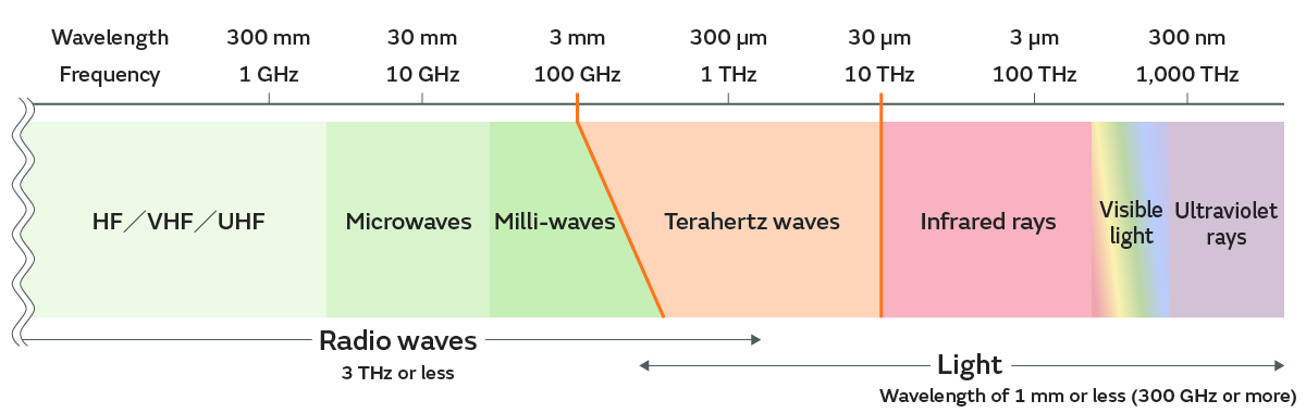
Radio waves are a form of energy like motion and heat. They are also called electromagnetic waves. (In fact, light is a type of electromagnetic wave.) Radio waves are defined as electromagnetic waves with a frequency of 3,000 GHz or less in Japan’s Radio Law and the Radio Regulations annexed to the International Telecommunication Convention. (We will explain later how to calculate the frequency.)
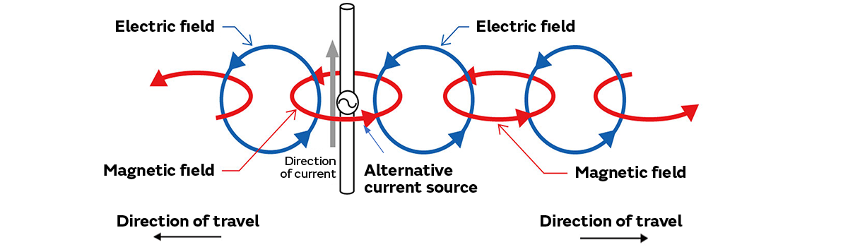
These radio waves are emitted from wireless devices. However, it is not easy to actually visualize them. Accordingly, we have explained the occurrence and transmission of radio waves from the phenomenon that occurs when sinusoidal alternating current is passed through a conductor rod such as metal to make it easier to picture.
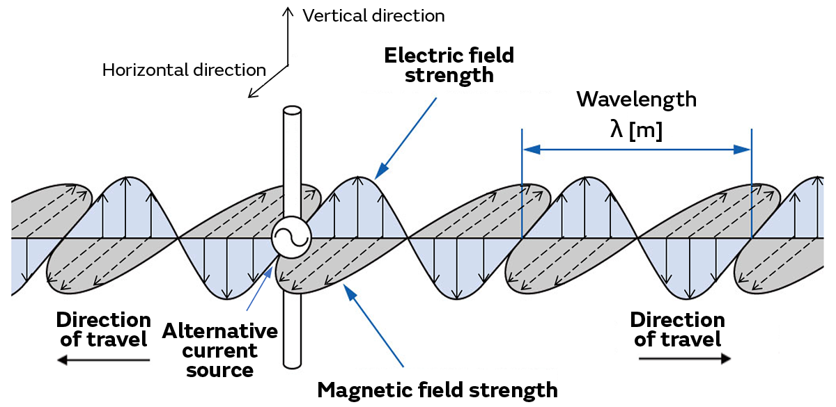
Figure 4 shows how radio waves travel at that time. In fact, radio waves extend out three-dimensionally. However, we focus on radio waves that travel when the conductor is vertically oriented here to reveal how they are transmitted. The electric field*2 and magnetic field*2 are maintained at right angles (orthogonally) to each other. Changes in the magnetic field create an electric field. Changes in the electric field then create a magnetic field. The repetition of this process allows radio waves to be transmitted as sinusoidal vibrations. We give below the main properties of radio waves.
[1] Radio waves are traverse waves. The amplitude (strength) of the electric field and magnetic field changes perpendicularly to the direction of travel, and the electric field and magnetic field then also transmit the radio waves perpendicularly to each other.
[2] The speed at which the radio waves are transmitted is the same as that of light.
[3] Radio waves have no transmission medium. (The air vibrates and is transmitted as waves. We then feel the sound when those waves enter our ears. The air at this time is referred to as the transmission medium.)
The properties of [3] are far from our everyday senses. Nevertheless, it is believed that radio waves, or electromagnetic waves, that are transmitted even in a vacuum such as outer space propagate while electric fields (space that electrical forces act) and magnetic fields (space that magnetic forces act) vibrate.
Incidentally, we stated that radio waves are electromagnetic waves with a frequency of 3,000 GHz or less at the beginning of this column. We can calculate this frequency (f) [Hz] using the formula of f = c/λ assuming the radio wave length (m) in Fig. 4 and the speed of light c (3 × 10⁸ m/s). Electromagnetic waves are classified into several types depending on their frequency and wavelength (Fig. 5).
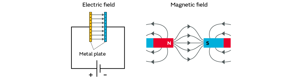
*2: Electric field and magnetic field: An electric field refers to a space where an electric force acts. A magnetic field refers to a space where a magnetic force acts. Fig. 6 is an image that indicates with arrowed lines the range of the electric field generated by the application of voltage and the range of the magnetic field generated around the magnet.
[Advanced Supplementary Information]
We often see an image of the transmission of radio waves that simply combines the phenomena of changes in the magnetic field creating an electric field and changes in the electric field creating a magnetic field in explanations of radio waves for beginners (Fig. 7). If you want to seriously study radio waves such as in relation to antennas, instead of such an image, it is important to have an image of the vectors that represent the strength of the electric and magnetic fields with arrows in Fig. 4—the electric field vector*3 and the magnetic field vector*3. (The image in Fig. 4 is derived from Maxwell’s equations*4.) According to this image, the radio waves used in satellite broadcasting, for example, are explained as circularly polarized radio waves that travel in a spiral pattern while the magnetic field vector in Fig. 4 rotates to the left or right.
*3: Electric field vector and magnetic field vector:
Both these vectors are vectors that represent the clockwise rotation and speed of rotation. (They are also called “rotation vectors” in this sense.) This does not mean that both indicate the direction in which an object or something else moves like with a velocity vector.
*4: Maxwell’s equations: These are the basic equations relating to electromagnetic fields that express all the relationships between electricity and magnetism. Coulomb’s law, which beginners to electromagnetism learn, can also be derived from these equations.
5. Data Transmission Direction: Duplex (Full Duplex and Half-duplex) and Simplex
5.1 Duplex Transmission
5.2 Simplex Transmission
6. What Is a Communication Protocol?
Column: History and Evolution of Wireless Communication