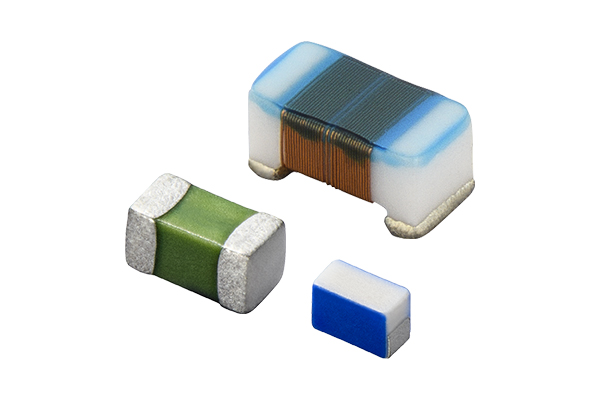
RF Inductor

INDEX
1.1.1 Ideal resistance characteristics in a direct current circuit
1.1.2 Ideal inductor/capacitor characteristics in a direct current circuit
It is no exaggeration to say that modern lifestyles and business as well as the operation and structure of society are built upon the utilization of precision electronic equipment such as smartphones and PCs. Advanced analog circuit technologies, or in other words, alternating current circuit technologies and high-frequency technologies using high frequencies in fact play a significant role in the evolution of such electronic equipment, and high-frequency technologies are essential to the development of precision electronic equipment that operates at high frequencies.
However, mastery of high-frequency technologies requires fundamental knowledge of electrical circuits, specific knowledge of high frequencies, and becoming accustomed to conventions, and the hurdle is undeniable. While pouring over texts with explanations of various aspects is one approach to overcoming this hurdle, such texts rarely include an explanation of the high-frequency characteristics of inductors and capacitors, which are basic electric circuit elements. Accordingly, this series will focus on these aspects with the goal of providing an explanation that can promote an understanding of high-frequency technologies. This series should prove useful to those who wish to broadly know and understand high-frequency technologies.
Content of this series
・[Impedance and Resonance], which explains the differences between the ideal and actual electrical characteristics and impedance of inductors and capacitors in an alternating current circuit using Ohm's Law in a direct current circuit, an example that electricity novices first encounter
・[S-Parameters and Impedance] derived from the S-parameters, which are a staple in high-frequency measurements of impedance including the high-frequency range, because these differences are seen particularly in such range
・[Inductor and Capacitor Equivalent Circuit Model], which explains the equivalent circuit model for Murata components composed of actual elements and ideal elements
The interior of familiar electrical and electronic devices consists of circuits and electrical circuits(*1) that operate using electricity, and there are many excellent texts that provide an overall basic explanation of such circuits. Here, we will take high frequencies as our point of view to provide an explanation that focuses on content relating to the high-frequency characteristics of resistance/inductors/capacitors, which are the basic circuit elements.
First, let us organize the following basic elements so that we may understand their overall relationship in an electrical circuit (Table 1).
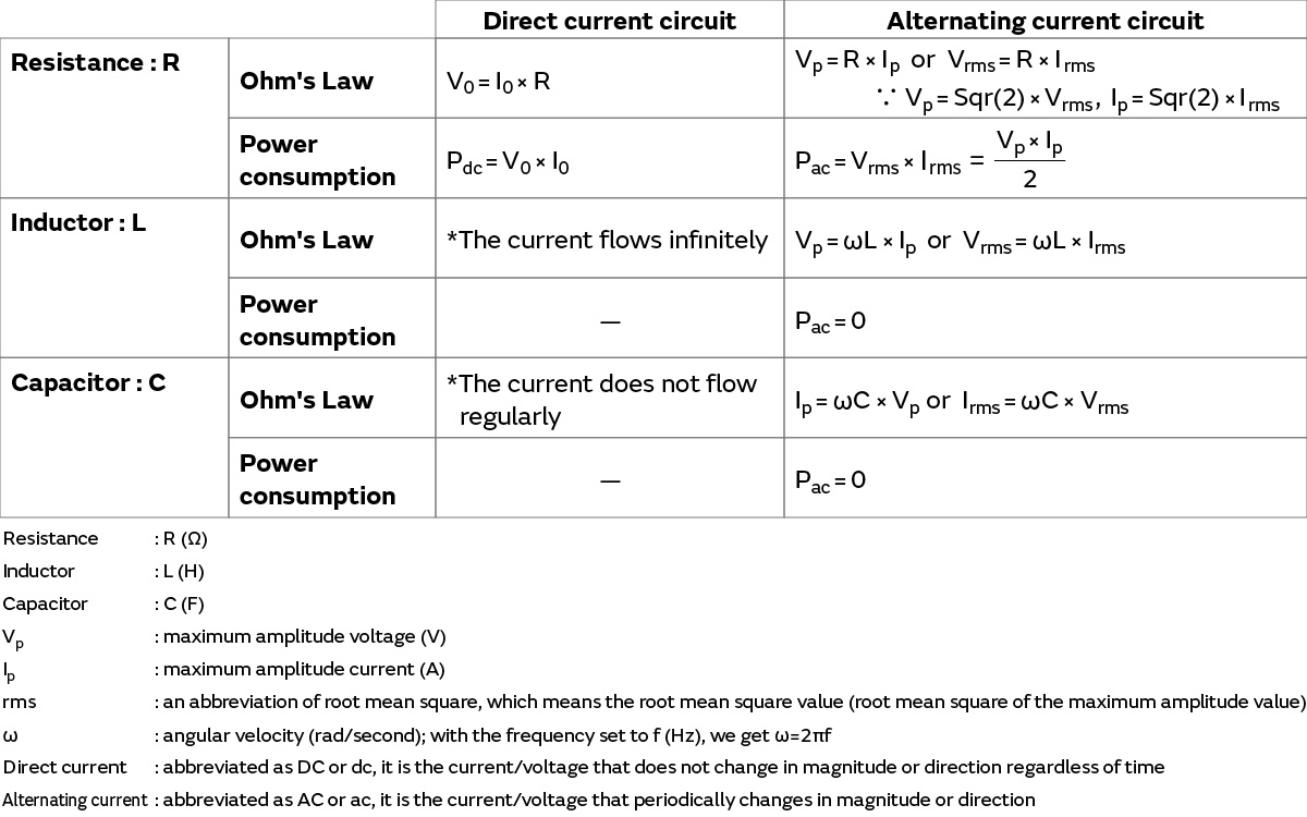
The individual elements of Table 1 are explained starting in section 1.1, while the main points are indicated here.
If we focus in particular on alternating current circuits, it can be said that the passive elements of resistance, inductors, and capacitors each have their own functions and operations. By combining these passive elements with active elements, various circuit characteristics that are required for electrical and electronic equipment are created.
*1 A representation of basic terminology about electricity in this series.
- If we respectively designate the internal circuits of electrical and electronic devices as electrical circuits and electronic circuits, then electronic circuits can be thought of as part of electrical circuits.
- Elements that are connected to a circuit are called "circuit elements"; transistors and ICs with switching and amplification functions are called "active elements"; and resistance/inductors/capacitors are called "passive elements" (or components).
- An electronic circuit is equipped with active elements, which can be thought of as a circuit that runs on a low voltage of tens of volts, for example.
- A circuit that is only connected to passive elements (or components) is called an "electrical circuit."
*2 The resistance/inductors/capacitors in Table 1 are assumed to be ideal circuit elements – ideal elements. The meaning of "ideal" is generally described as follows.
・The resistance, inductor, and capacitor possess only their respective component characteristics.
・Even if the current flowing through each element, the applied voltage, operating temperature, and other conditions change, the characteristics of each element do not fluctuate or deteriorate.
・Rated values such as the conditions and limits for the use of each element are not considered.
This section provides a simple explanation of the direct current circuit items in Table 1, or in other words, the operation of resistance, inductors, and capacitors as ideal circuit elements in a direct current circuit.
This section covers the operation of a direct current circuit that connects an ideal resistance to a direct current power supply, which is a topic that electricity novices learn for the first time.
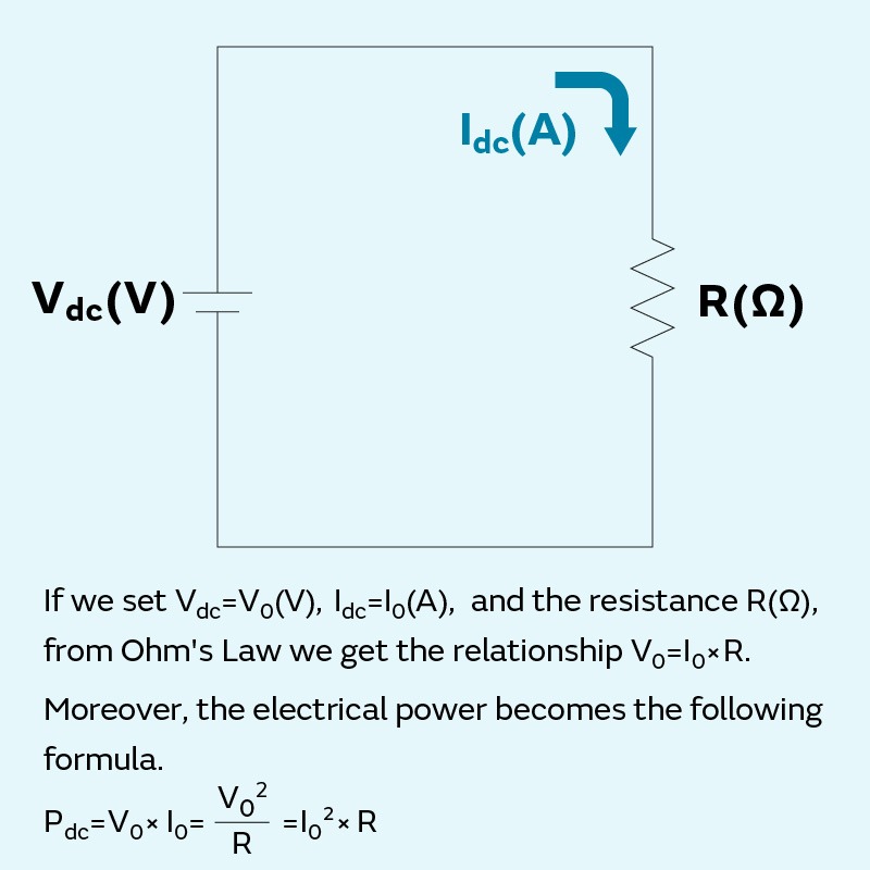
If we set the value of the direct current power supply voltage Vdc to V0 (V), the value of the current Idc flowing through the circuit to I0 (A), and the resistance value of the ideal resistance with a resistance component only to R (Ω), we get the following relationship (Ohm's Law) (Figure 1-1).
V0 = I0 × R
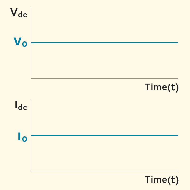
If we assume that the direct current power supply is an ideal power supply that continuously supplies the constant voltage V0 regardless of the time, then the current I0 also becomes a constant value at all times (Figure 1-2). Moreover, because I0 = V0/R, the value of the current I0 decreases when the value of the resistance R increases and vice versa.
If we set the electrical power to Pdc (W), we can obtain it as the product of the voltage and current in the form of Pdc = V0 × I0. Moreover, if we apply Ohm's Law, we can derive the following relationships.
Pdc = V02/R
Pdc = I02R
The electrical power of this circuit is consumed (converted into heat) by the resistance. If, for example, we increase the voltage applied to the resistance or the current that is flowing by three times, then the electrical power increases by nine times (3 × 3) because the electrical power that becomes heat increases exponentially.
[Additional remarks]
In high-frequency circuits that mobile phones and other devices are equipped with, it is difficult to accurately measure the voltage and current due to high-frequency specific phenomena. Therefore, it is common in high-frequency circuits such as these to measure with electrical power that promises stable and accurate measurement. This point is addressed in the section on S-parameters, which is explained separately.
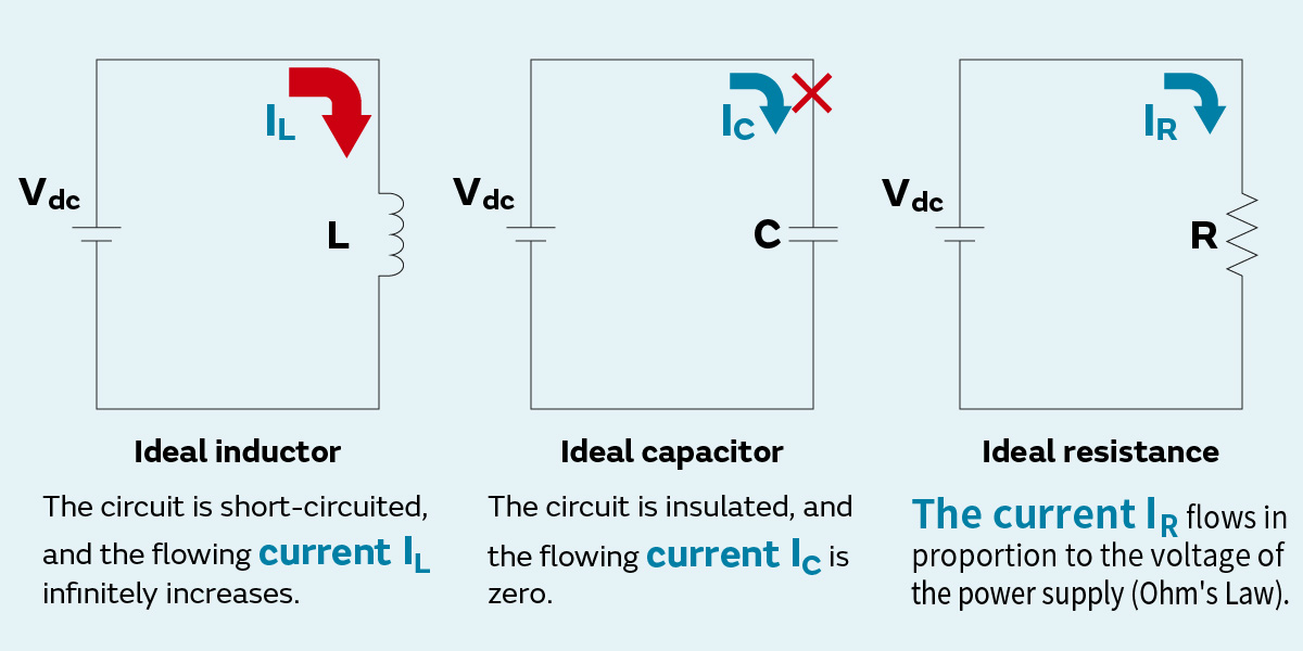
So, what happens if we connect an inductor to a direct current power supply and do the same with a capacitor (Figure 1-3)?
First, we will think about a direct current circuit connected to an ideal inductor.
An inductor within a direct current circuit becomes a mere conductor. Moreover, because it does not possess any non-inductance components, the resistance value is zero. Therefore, the circuit enters a short-circuit state (short), and in the case of a power supply that tries to maintain a constant voltage, the current flowing through the circuit (IL) infinitely increases. (It can be said that actually building this circuit without any consideration of safety is dangerous.)
Next, we will consider a direct current circuit connected to an ideal capacitor.
Because a capacitor within a direct current circuit has a dielectric substance, which is an insulator, sandwiched in between the internal electrodes, the wiring is disconnected and in an insulated state. The circuit enters an open-circuit state (open), and in the case of a power supply that tries to maintain a constant current, the applied voltage infinitely increases because the flowing current (IC) is zero.
(Similar to the example above, it can be said that building this circuit is dangerous.)
The "high frequencies" mentioned in the opening sentence of this page are often used, so we would like to address that topic here.
As the name would indicate, "high frequencies" refers to frequencies that are high, but the meaning is vague. In fact, there is no clear definition as to what range of frequencies "high frequencies" refers to. However, such frequencies generally seem to be thought of in the following manner.
(1) In some cases, the term simply refers to high frequencies. For example, the sub-GHz (frequencies of less than 1 GHz) radio-wave frequencies of mobile phones and millimeter-wave radar (60 GHz), etc. are often called high frequencies.
(2) Depending on the field of application, the phrase "high frequencies" may be used in a relative sense even for frequencies that are lower than those described above in (1). For example, in electric power-related fields, commercial frequencies at 50 Hz/60 Hz are called "low frequencies" while the frequencies from several kHz to tens of MHz are called "high frequencies."
Meanwhile RF (radio frequency) is also often used as a term meaning high frequency. The term RF also lacks a clear definition. Examples of how RF is used include mobile phones mentioned above in radio engineering applications, electric scalpels (300 kHz - 5 MHz) in the beauty and medical fields, and RF sputter deposition systems (13.56 MHz) for industrial applications, and they are used across broad frequency ranges that combine examples (1) and (2) above (examples of RF usage include Murata's component modules consisting of RFIDs/RF inductors/millimeter-wave RF modules/RF switches).
The opening sentence is written with (1) in mind, but in this series, "high frequencies" broadly refers to a range of frequencies similar to RF.
<Next article> A brief explanation of the electrical characteristics of resistance, inductors, and capacitors in an alternating current circuit.