NFG0QHB372HS2

Noise suppression technologies/case study introduction (Consumer)
INDEX
Effective measures for suppressing noise occurring during USB4 communication are as follows:
These key points are necessary for effective noise suppression.
The simplified diagram below shows an example of common mode choke coil (CMCC) installation locations for the combination of a device and a host capable of USB4, USB 3.1 Gen 2, PCI Express, and DisplayPort communication.
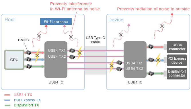

Noise suppression can be implemented using a compact, slim type having a size of 0.65×0.50×0.30 mm with dimensional error of ±0.05 mm without affecting the signal waveform of the high-speed differential transmission line.
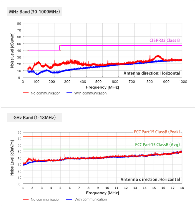
No noise exceeding the standard values was observed in the MHz or GHz bands.
This enabled us to ensure sufficient margin, and we are highly confident that radiated emissions will not be an issue for USB4.
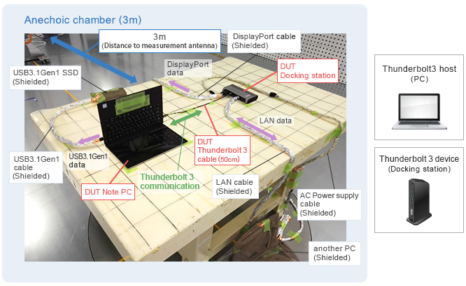
Next, to examine the effect of intrasystem EMC, we conducted a noise assessment using a Thunderbolt 3 compatible add-in card in the place of USB4.
The add-in card has a Thunderbolt 3 compatible IC only.
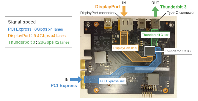
In this configuration, the PCI Express signal (8 Gbps x 4 lanes) and DisplayPort signal (5.4 Gbps x 4 lanes) are input to the Thunderbolt 3 IC on the card, and the Thunderbolt 3 IC generates a Thunderbolt 3 signal (20 Gbps x 2 lanes) that is output from a Type-C connector.
To check the impact of noise radiated from the board wires, the DUT only was housed in a shield box, and the Wi-Fi reception sensitivity of a nearby smartphone was measured.
In notebook PCs that are expected to include USB4, there is a growing trend to install the Wi-Fi antenna on the main board instead of on the display, and the distance between the differential line and antenna is expected to approach around 5 cm.
For this reason, this assessment was conducted with the board wires and smartphone separated by 5 cm.
(This simulates the distance between the antenna and signal line inside a notebook PC.)
