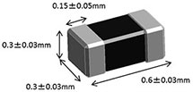
BLF03VK600SNL
Noise suppression technologies/case study introduction (Consumer)
INDEX
Today, wireless LAN capabilities are being added to growing numbers of smartphones and other digital devices.
And, in certain regions, technology using the 5 GHz band for LTE communication (LAA/LTE-U) has been adopted for enabling higher speeds for data communication, and wireless communication in the 5 GHz band is expected to continue to grow even more in coming years.
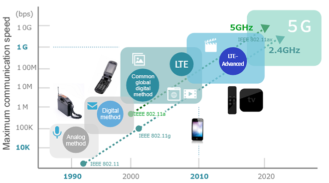
The 2.4 GHz band is still the most common for wireless LANs, but doesn't it seem that there are many users who have experienced communication disruptions and usability problems?
Do communication disruptions no longer occur or occur less often when using wireless in the 5 GHz band?
This paper will describe noise problems that occur in communication using the 5 GHz band and present several solutions.
We examine the case for noise issues that occur when high-speed data communication is performed indoors using a wired interface and the case for noise issues that occur in environments with multiple wireless communications.
Higher drive frequencies are being supported by individual electronic devices indoors, and there are concerns about the occurrence of noise at high frequencies. Also, as explained later, there have been cases where the wireless LAN 5 GHz band and the LTE 5 GHz band are used simultaneously.
Some of the expected issues that occur when this happens are as follows.
Next, we will examine some specific cases where noise occurs.
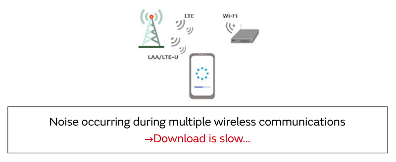
First, we will present the case for multiple wireless communications.
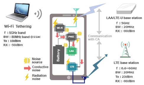
As mentioned at the outset, although we are quite familiar with Wi-Fi for wireless communication using the 5 GHz band, use of the 5 GHz band has also been determined for the LTE system, which is used in smartphones.
Usage has already started in areas and devices in some overseas regions, and this is expected to enable even faster data communication.
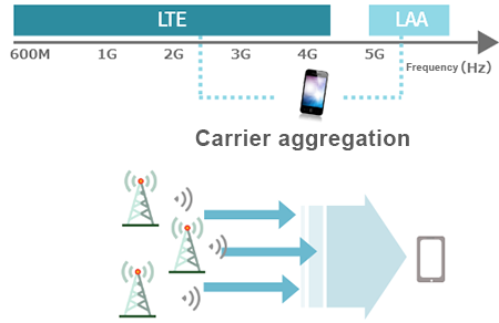
LTE using the 5 GHz band is called LAA or LTE-U, and it is a technology that enables high-volume communication through existing LTE and carrier aggregation. When this is performed, simultaneous use with Wi-Fi is also expected, and so the circuits for the three systems of LTE, LAA, Wi-Fi are running.
In this state, can wireless communication be performed without any problems?
| Item | Band | Name | Downlink (MHz) | ||
|---|---|---|---|---|---|
| Low | Mid | High | |||
| LTE-U | 252 | Unlicensed NII-1 | 5150 | 5200 | 5250 |
| 255144 | 255644 | 256143 | |||
| 255 | Unlicensed NII-3 | 5725 | 5787.5 | 5850 | |
| 260894 | 261519 | 262143 | |||
| LAA | 46 | TD Unlicensed | 5150 | 5537.5 | 5925 |
| 46790 | 50665 | 54539 | |||
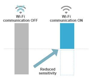
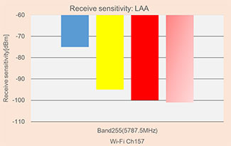
This figure shows the measurement results for LAA reception sensitivity when LAA communication is started while Wi-Fi communication is already running.
We found that the reception sensitivity was reduced when Wi-Fi communication was turned on.
When the reception sensitivity is reduced, if the signal strength from the base station or access point is weak, communication cannot be performed properly, and the data rate will be slowed, which could be stressful for some users.
This situation occurs because Wi-Fi and LAA are communicating using the same frequency, and this is due to the effect of noise generated when signals in the 5 GHz band interfere with each other or the wireless circuits are running.
Previously, there were no wireless circuits at the same frequency that were running simultaneously, and so problems were not observed, but we think that remedies will be required.
To confirm the causes for reduced reception sensitivity, we conducted an examination using a system simulation. In the simulation, the communication characteristics are obtained for an environment where no noise occurs because each block is operating in the ideal state.
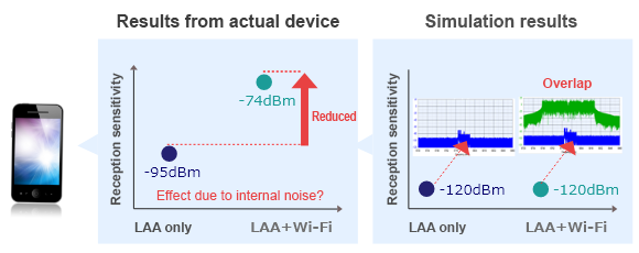
Looking at these results, whereas the reception sensitivity was reduced in actual devices, this change is not observed in the simulation, and this indicates that the reduction in reception sensitivity does not arise simply due to simultaneous communication by LAA and Wi-Fi.
And so, we suspected that the cause is noise that occurs when each circuit is running, and so we conducted a noise study on the inside of an actual device.
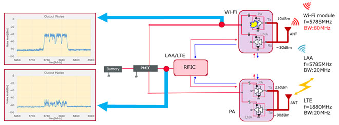
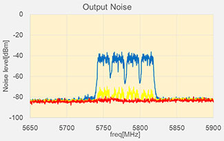
The figure above shows a schematic diagram of the LTE, LAA, and Wi-Fi circuit blocks.
Measurements were conducted on the noise of the power line when communication was performed under the conditions shown in the figure at right. Looking at the results, the power line of the Wi-Fi module has the highest level on the spectrum, and the same spectrum was observed for the power line of the RFIC. This matches the bandwidth of the Wi-Fi communication signal, and this suggests that noise originating from Wi-Fi is transmitted to the power line and is flowing into the circuit blocks.
In other words, we can summarize the points about noise generation and the conductive path as follows.
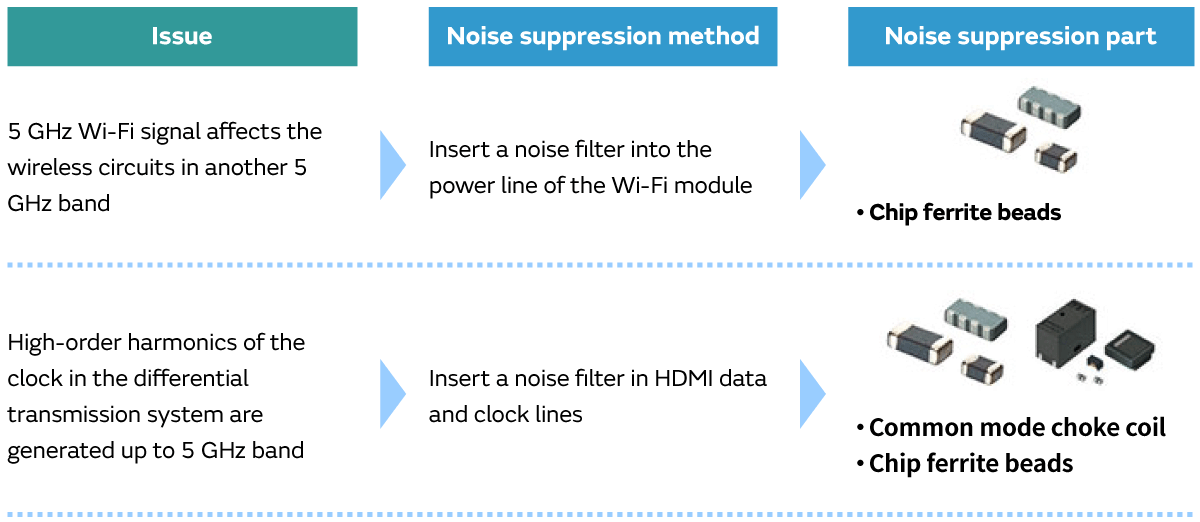
Because we discovered the noise generation and conductive path, we inserted a noise filter to reduce the noise conduction.The noise filter was inserted in the power input unit of the RF circuits.
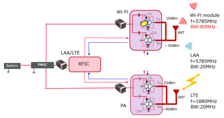
The Murata BLF03VK series for noise reduction in the 5 GHz band was used for the noise filter.
It can be verified that the reception sensitivity is improved when the conductive noise is reduced.
In this way, in environments using multiple wireless systems where the frequencies overlap, noise can be conducted from one communication circuit to another and adversely affect it, and so an effective counter-measure is to put a noise removal filter capable of removing the specific frequency band into the power line.
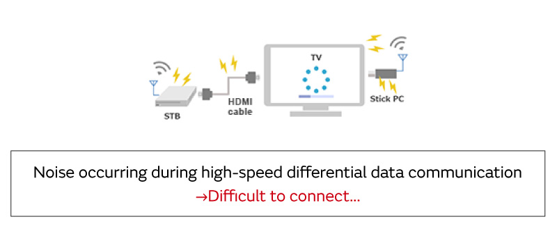
Next, we will present issues that occur when performing HDMI communication in a home environment.
HDMI is widely used as a video system interface for connecting BD recorders, STBs, and TVs. It is also used as a stick PC interface for converting TVs into PCs. In the latest standard, HDMI version 2.1 was announced, but many users are probably using 2.0 or 1.4.
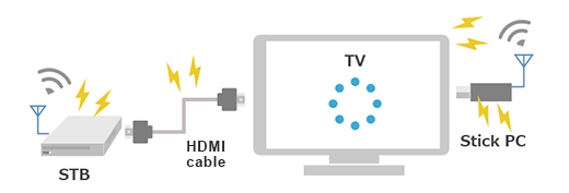
The table below shows the results when a stick PC was inserted into a TV and the Wi-Fi reception sensitivity was measured during HDMI communication. As shown in the table, the sensitivity is reduced by slightly less than 4 dB, and noise occurs in conjunction with HDMI circuit operation, which results in reduced reception sensitivity.
| Reception sensitivity(36CH) | |
|---|---|
|
HDMI signal not available |
-74dBm |
|
HDMI signal available |
-70.4dBm |
| 3.6dBm Reduced |
Then, what is happening during HDMI communication? We investigated the signal state.
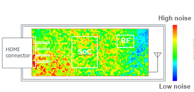
This shows a mapping of the magnetic field distribution for the PCB surface of the stick PC that was mentioned above. It consists of an HDMI connector, wireless circuit, and control IC, and because it is packed into a size of about 15 cm × 8 cm, all circuits are in close proximity to each other.
As a result, if noise occurs inside the device, it is coupled to the antenna and other RF circuits and easily disturbs wireless communication.
In this stick PC, because it appears that noise is distributed over the entire PCB, we affixed an electromagnetic wave absorbing sheet to the entire PCB and verified whether the level of noise coupled to the antenna had changed.
Doing so, the noise level dropped by about 10 dB, and this indicated that noise was coupled from the PCB to the antenna.
As explained above, we affixed an electromagnetic wave absorbing sheet to the entire PCB and verified the improvement results, but when we consider that noise is generated when HDMI is running, we suspect that noise is being conducted in the signal line.
And so, we decided to try using noise reduction filters for the HDMI signal and clock lines. Two types of filters were used -- common mode choke coil and Pi low pass filter (LPF). A common mode choke coil is a filter that is effective for removing common mode noise only without effecting the signal waveform of the differential transmission line.
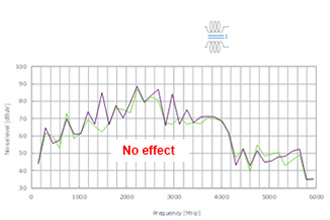
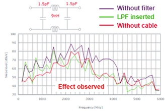
Although no effect was observed using the common mode choke coil, the pi LPF was effective at reducing noise. In other words, this indicates that differential mode noise is being conducted in the stick PC that was being evaluated.
* The common mode noise component may be dominant for some target devices, and so a common mode choke coil may be effective in some cases.
Because we found that the differential mode noise was dominant, to reduce noise, we must select a filter that does not affect the signal.
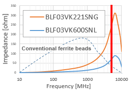
At Murata, we have developed a new BLF03VK product series for providing effective noise reduction in the 5 GHz band. We selected an item with these characteristics from this product series.
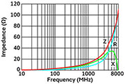
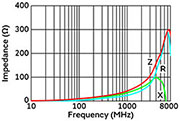
【Features】Instead of the impedance increasing from low frequencies like conventional ferrite beads, the material and internal structure have been designed so that the impedance increases at 5 GHz.
| Murata Part Number | Impedance@5GHz (ohm_typ) | Rated Current (mA) | DC Resistance (max.) (ohm) |
|---|---|---|---|
| 220 | 800 | 0.155 | |
| 60 | 1200 | 0.065 |
This examines the filter for the 5 GHz band only, but our product lineup also includes filters for the 2.4 GHz band and 700 MHz band.
Information about other product series is available here
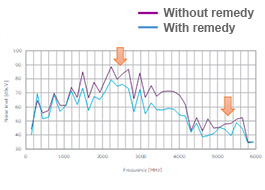
The figure below shows the results when the above-mentioned pi filter was replaced by the BLF03VK and the noise reduction effects were verified. It was verified that the high-frequency component of the clock was reduced by about 10 dB.
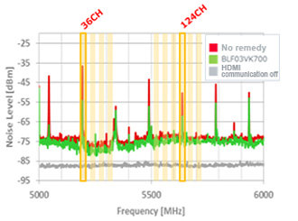
The area filled in with yellow indicates the channels used by Wi-Fi (11ac), and noise can be seen in channels 36 and 124.
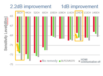
This resulted in a particularly large reduction in reception sensitivity in channels where noise occurred, but by applying a noise suppression using the new noise filter, the narrow-band noise originating from the HDMI clock was reduced for enabling higher reception sensitivity.
Because the filter was inserted in the HDMI data and clock lines, the signal quality was checked.
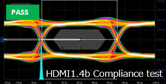
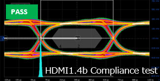
The results for the HDMI 1.4 pre-compliance test that was conducted show that the test was passed without hitting the eye mask even when a filter was used.
This is partly due to the small impedance in the low-frequency band by the BLF03VK series, and the need is expected to grow for filters where the impedance increases only in the specific bands where noise will be removed for ensuring signal quality.
* However, the waveform when the filter is actually used will vary depending on the IC and set environment, and so verification is necessary.
We presented two examples of remedies for reducing the noise in the 5 GHz band.
Previously, the 5 GHz frequency was not commonly used, and so people tended to think that noise issues were unlikely to occur, but when we actually examined the noise, we found that noise was occurring in both the signal and power systems.
Even if the 5 GHz band is selected for providing stable, high-speed communication, maximum performance will unable to be attained if noise is present.
The noise suppression products presented here can be used to create a low-noise environment for ensuring stable communication quality.
The BLF03VK is a noise filter that was designed for effective removal of noise in the 5 GHz band.