Capacitor
PRODUCT FOCUS
This article introduces high and medium voltage low-loss multilayer ceramic capacitors (MLCC) that are optimal for resonant circuits used in automotive OBCs, wireless power transmission, and servers. It provides a detailed explanation of the characteristics and selection criteria when utilizing these capacitors in high-power LC and LLC resonant circuits, which have been increasingly prevalent in recent years.


In recent years, the use of resonant circuits has been increasing.
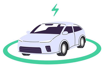
In high-efficiency power supplies of 100W or more, such as automotive OBCs for EVs and PHVs (electric vehicles and plug-in hybrid vehicles), server power supplies, and power supplies for large equipment, LLC resonant circuits are widely adopted. It is estimated that their adoption rate exceeds 90%. Additionally, in wireless power transfer (WPT), LC resonant circuits are used for transmitting and receiving large amounts of power. WPT-enabled products have expanded beyond small devices like smartphones and tablets to include larger products such as automobiles and transport robots used in manufacturing processes.
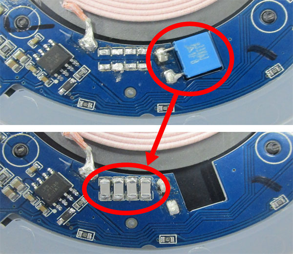
As various types of resonant circuits like LC and LLC resonate become more prevalent, there is a growing demand for resonant capacitors (capacitors used in resonant circuits) that offer stable capacitance values above 10nF along with low-loss performance. Traditionally, film capacitors were the only option available; however, multilayer ceramic capacitors have now become mainstream due to their diverse advantages. Specifically, multilayer ceramic capacitors are preferred for resonant circuits that require high power density.
This technical article will explain the benefits of using multilayer ceramic capacitors as resonant capacitors while providing insights into their characteristics, points for effective utilization, selection considerations, and recommended product lineup.
For example, in resonant circuits used in products that handle high currents, such as automotive WPT, the voltage applied to the capacitors (V(p-p)) can be quite high, ranging from several hundred volts (p-p) to 10,000 volts (p-p), with some cases reaching up to 10,000 V(p-p). Since the rated voltage of multilayer ceramic capacitors is 630 Vdc or 1000 Vdc, it is necessary to connect capacitors in series to ensure that this V(p-p) remains within the rated voltage limits when operating at high voltages.
When capacitors are connected in series, their effective capacitance decreases; therefore, parallel connections are needed to achieve the required capacitance. As a result, it has become common for resonant capacitors to be used in multiple series and parallel configurations, leading to a demand for products with smaller footprints.
In the automotive market, for automotive WPT, the resonant frequency is fixed at 85 kHz according to international standards. However, for EV and PHV OBCs, the resonant frequency varies by manufacturer, ranging from 60 kHz to 400 kHz. In these applications, high-frequency high voltage is applied to the capacitors, which can lead to increased self-heating.
Therefore, resonant capacitors are required to have lower loss characteristics and to minimize the rise in self-heating during long-term use.
Characteristics of Multilayer Ceramic Capacitors
・Small mounting area (volume)
・Low heat generation (low ESR)
・Low ESL
・Excellent long-term reliability
・High maximum operating temperature
Multilayer ceramic capacitors have superior long-term reliability compared to film capacitors due to their high maximum operating temperature and low heat generation. Additionally, they are characterized by a smaller volume and lower ESL for products with the same capacitance. Because of these features, multilayer ceramic capacitors are widely used as resonant capacitors in high-power resonant circuits.
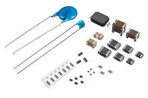
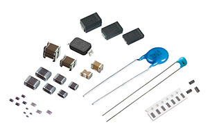
As mentioned above, resonant capacitors with low loss and less self-heating are required for high-power resonant circuits such as WPTs for automobiles and OBCs for EVs and PHVs. To meet such demand for resonant capacitors, Murata offers a lineup of medium- to high-voltage multilayer ceramic capacitors with rated voltages of 630 Vdc and 1000 Vdc and using low-loss materials.
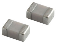
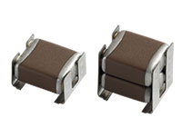
Chip Multilayer | Metal Terminal Type Multilayer | |
|---|---|---|
Appearance |
|
|
Operating | −55 to +125°C | −55 to +125°C |
Rated Voltage (DC) | 630 V | 630 V |
Temperature Range | C0G (EIA): 0±30ppm/°C | C0G (EIA): 0±30ppm/°C |
Capacitance Range | 5.6 to 10nF (3216M size) | 15 to 54nF |
There are two common product forms: the standard chip type and the chip type with metal terminals (see Table 1). The metal terminal type allows for stacking of large-size chips (5750M size), which not only reduces the mounting area but also helps mitigate the risk of 'solder cracking' that is a concern in the automotive market.
Large products such as automotive OBCs, server power supplies, and power supplies for large equipment that incorporate resonant circuits require long-term reliability in capacitors due to their extended usage periods. For these multilayer ceramic capacitors, a target lifespan of 10 years is set based on continuous use.
Including the products introduced above, there are important considerations when selecting capacitors (resonant capacitors) for use in resonant circuits. Incorrect selection of resonant capacitors in high-power applications can lead to smoke or fire incidents in the equipment. This is also true for multilayer ceramic capacitors, which offer low heat generation and long-term reliability; therefore, it is essential to select them with careful consideration of their characteristics.
We will explain two items that we consider particularly important: 'self-heating of capacitors' and 'voltage derating curves.'
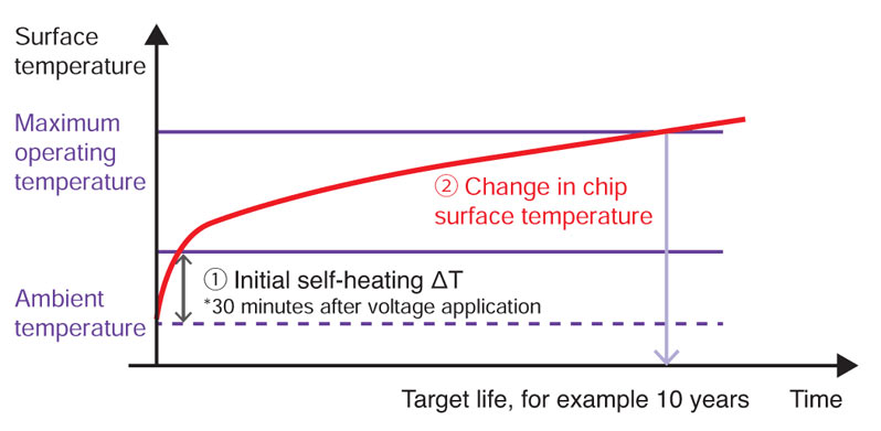
Resonant capacitors used in high-power applications exhibit an increase in self-heating after the initial heating that occurs immediately upon voltage application. While an increase in self-heating is inevitable for multilayer ceramic capacitors, voltage and frequency conditions that exceed the maximum operating temperature of 125°C within the target lifespan (for example, 10 years) should be avoided (see Figure 1).
Murata's multilayer ceramic capacitors define the allowable voltage Vdc as the voltage at which the surface temperature of the capacitor reaches the maximum operating temperature of 125°C over its target lifespan. When selecting a capacitor, it is essential that the applied voltage V(p-p) remains within this allowable voltage.
We provide "voltage derating curves" (see Figure 2) for each item, showing allowable voltages according to frequency, which are detailed in product specifications and on our website's spec sheets.
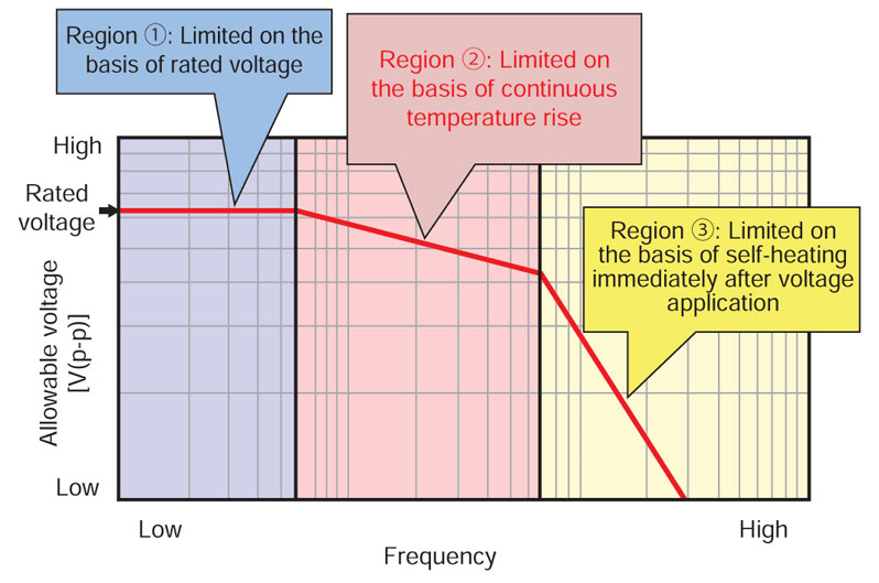
This is our perspective on the relationship between allowable voltage and frequency. The 'voltage derating curves' shown in Figure 2 generalize the allowable voltage graphs set for each item, which can be classified into three regions based on frequency range.
Due to the low frequency of several 10 kHz or less, the self-heating of the capacitors is minimal, and the rated voltage becomes the allowable voltage. However, cases where multilayer ceramic capacitors designed for medium and high voltage low loss are used in this low frequency range as resonant capacitors are rare.
The self-heating immediately after voltage application is within ΔT of 20 degrees*1, but this area exhibits an increase in self-heating due to high voltage application ranging from several 10 kHz to several 100 kHz. In this region, the allowable voltage is defined as the voltage at which the surface temperature of the capacitor reaches the maximum operating temperature of 125°C over its target lifespan (in the case of the products introduced here, a target lifespan of 10 years). Most cases where multilayer ceramic capacitors designed for medium and high voltage low loss are used as resonant capacitors fall within this region.
*1 We require that, regardless of low loss and high dielectric constant chip capacitors, the operating conditions ensure that the self-heating of the capacitor remains within ΔT of 20 degrees.
When the frequency is further increased, the self-heating of the capacitor immediately after voltage application exceeds ΔT of 20 degrees. As mentioned earlier, we require that, regardless of low loss or high dielectric constant chip capacitors, the operating conditions ensure that the self-heating of the capacitor remains within ΔT of 20 degrees. For medium and high voltage low-loss multilayer ceramic capacitors, the allowable voltage is defined as the voltage at which self-heating reaches ΔT of 20 degrees; therefore, it is necessary to select products such that their temperature remains below this threshold.
As explained so far, selecting resonant capacitors involves considering various characteristics, which increases the difficulty of component selection. This can be a factor that complicates technological advancements in rapidly growing areas such as automotive OBCs, server power supplies, and power supplies for large equipment. In particular, two points can be highlighted.
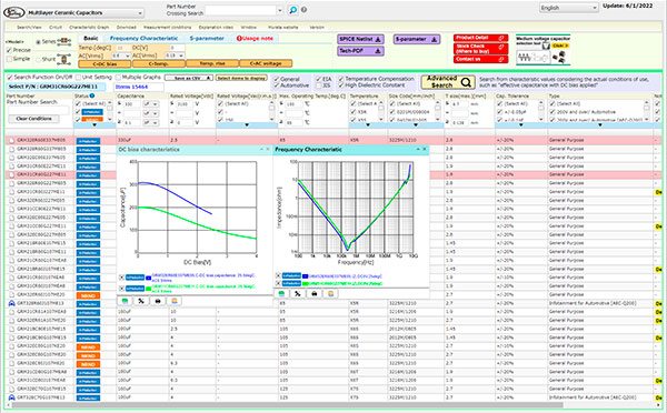
Murata has developed a tool called "Simsurfing" to support our customers in selecting the most suitable resonant capacitors for their operating environments. By simply inputting the operating voltage, temperature, and required capacitance of the resonant capacitor, the tool displays the optimal products along with the recommended number of series and parallel connections. This tool helps reduce the burden on customers during part selection and design.
The design support software, SimSurfing, can be found here.
Click here to search for chip capacitor type products.
Click here to search for products with metal terminal types.
*The content of the article is based on information available at the time of publication. Please note that it may differ from the latest information.