Noise suppression solutions compatible with the USB 3.2 RFI System-Level Test
External I/O connector trends
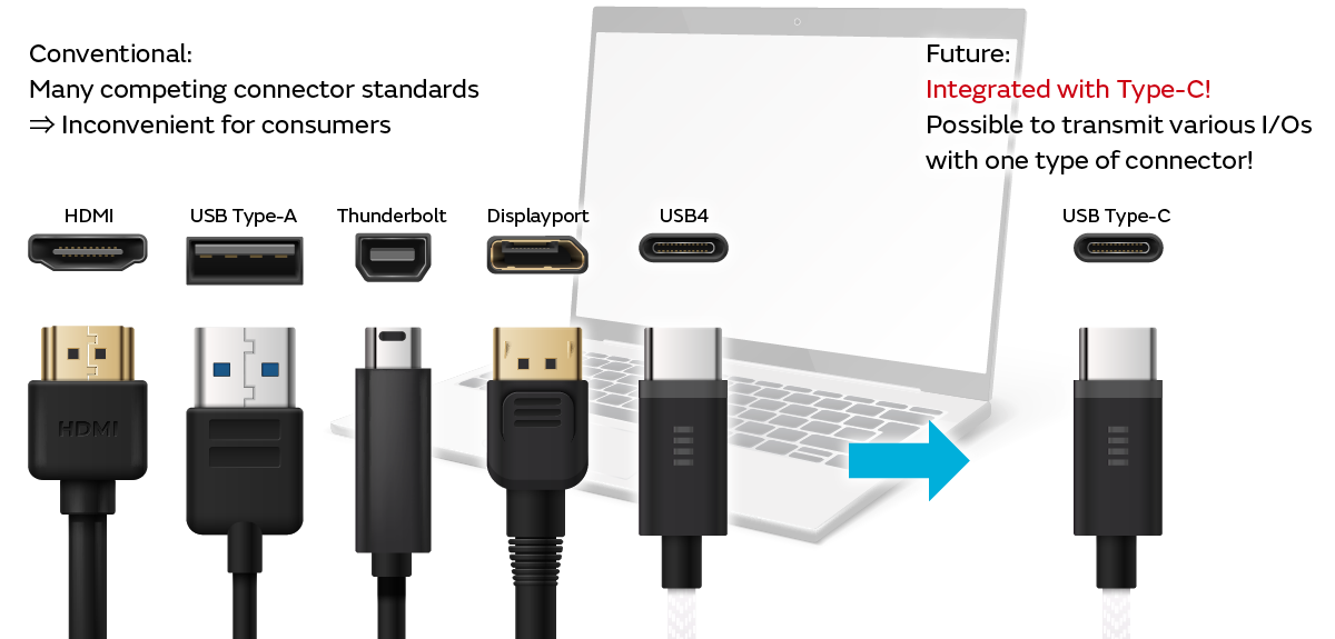
There are various standards including USB, HDMI, and DisplayPort for the external interfaces used in electronic devices represented by laptops. In addition, the connectors for each interface also have their own respective standards. There are many competing connectors and cables with various shapes. In this case, many cables are connected for each purpose to one electronic device, which is very cumbersome and inconvenient for consumers.
Accordingly, a movement has been underway in recent years to unify the many competing connector standards into one type of Type-C connector to allow support for various interfaces with one Type-C cable. It is already possible to realize charging, video transmission, and data transfer with one cable in laptops. Starting with this, it is expected that this will spread to other electronic devices.
The European Commission law making it obligatory to unify charging standards to Type-C is boosting this movement. It is anticipated that the Type-C connector will become the de facto standard around 2024.
New noise standard relating to USB Type-C
A new noise standard relating to USB communication has been formulated by the USB-IF due to the spread of Type-C. It is the USB3.2 RFI System-Level Test (RFI test). This is a standard that takes into account the problem of noise during USB3.2 communication causing malfunctions by interfering with surrounding wireless devices such as mice and headsets. This interference problem has surfaced in recent years. Electronic device manufacturers are focusing their efforts on improving quality with their own indicators. Communication quality care until now was only based on the judgment of each manufacturer. However, it is necessary to set a certain level for USB-derived noise. This is the purpose of formulating the standard this time.
The devices targeted by this standard are laptops, tablets, smartphones, docking stations, and similar that have a Type-C connector and support 5 Gbps or more. As a result, to ship devices it is necessary to satisfy the level in this standard to obtain USB logo certification for Type-C.
* Interference problems also arise when using conventional connector standards like Type-A. However, they are not covered by this standard.
- New noise standard: USB 3.2 RFI System-Level Test (RFI Test)
- Standards body: USB-IF
- Devices targeted by this standard: Laptops, tablets, smartphones, docking stations, etc.
(Equipped with a Type-C connector and supports 5 Gbps or more)
[Purpose]
Standardization of the wireless communication quality level / Impact on the market

Overview of the RFI test
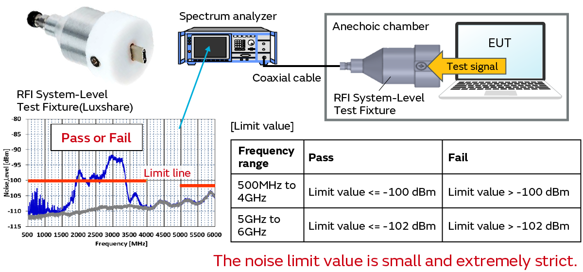
We conduct an evaluation using the RFI System-Level Test Fixture (hereinafter "Fixture") in the RFI test.
This Fixture is an official jig established by the USB-IF. It converts Type-C connectors to SMA. As shown in the top right of the figure below, we insert the Fixture into the Type-C receptacle of the EUT and connect it to the spectrum analyzer via a coaxial cable in the evaluation system. The Fixture and the EUT are installed in an anechoic chamber.
At this time, a test signal is transmitted from the EUT and a judgment is made as to whether the noise observed with the spectrum analyzer satisfies the limit value.
This is an area where noise regulations have not been established up to now. Moreover, as shown in the bottom right of the figure below, the limit value is extremely small. Therefore, it is conceivable that it will not be possible to satisfy the standard and that new noise problems may arise with the conventional designs of each electronic device manufacturer. Accordingly, we introduced the measurement equipment of this standard and worked to clarify the RFI test measurement principles and noise problems.
RFI test measurement principles
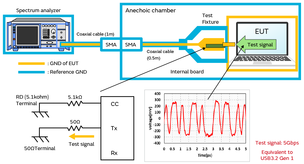
We give the RFI test measurement principles. The figure below shows an illustration of the RFI test measurement system.
The part shown in orange is the GND of the EUT. This conducts to the Type-C connector and core wire of the Fixture. The part shown in blue is the reference GND for the measurement. The anechoic chamber, the outer shield of the coaxial cable, and the external housing of the Fixture are at the same potential. Moreover, the part shown in green inside the Fixture is the internal board. It plays the role of terminating the test signal output onto Tx1± from the EUT with a 50 Ω resistor mounted on the board. The test signal (CP0) is a 5 Gbps random high-speed signal. This is a signal equivalent to USB 3.2 Gen 1.
Accordingly, we can see that the RFI test observes the noise conducted to the Type-C connector GND of the EUT when USB3.2 Gen1 signals are transmitted onto Tx1±.
川越光科技有限公司_Advantage of RFI System Level Test Solution
Noise generation mechanism
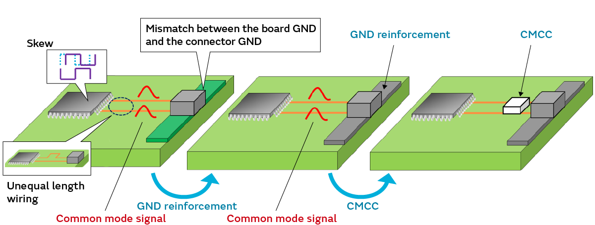
We explain below the noise generation mechanism in the RFI test. There are two factors that generate noise.
The first is the common mode signals generated by unequal length wiring and the skew between the signals possessed by the ICs. The other is mode conversion from an impedance mismatch between the board GND and connector GND.
Moreover, equipping a common mode choke coil (CMCC) and reinforcing the GND of the Type-C are effective as noise suppression measures. It is possible to suppress the noise that is conducted to the GND of the Type-C connector GND with these noise suppression measures.
Factors that generate noise 1:
Mode conversion due to impedance mismatch between the board GND and the connector GND
⇒ Noise suppression measure: Match the impedance by reinforcing the GND
Factors that generate noise 2:
Common mode signals that arise due to unequal length wiring and skews between the signals possessed by the ICs
⇒Noise suppression measure: Attenuate the common mode signals by equipping a CMCC onto the signal wiring
Noise mechanism investigation
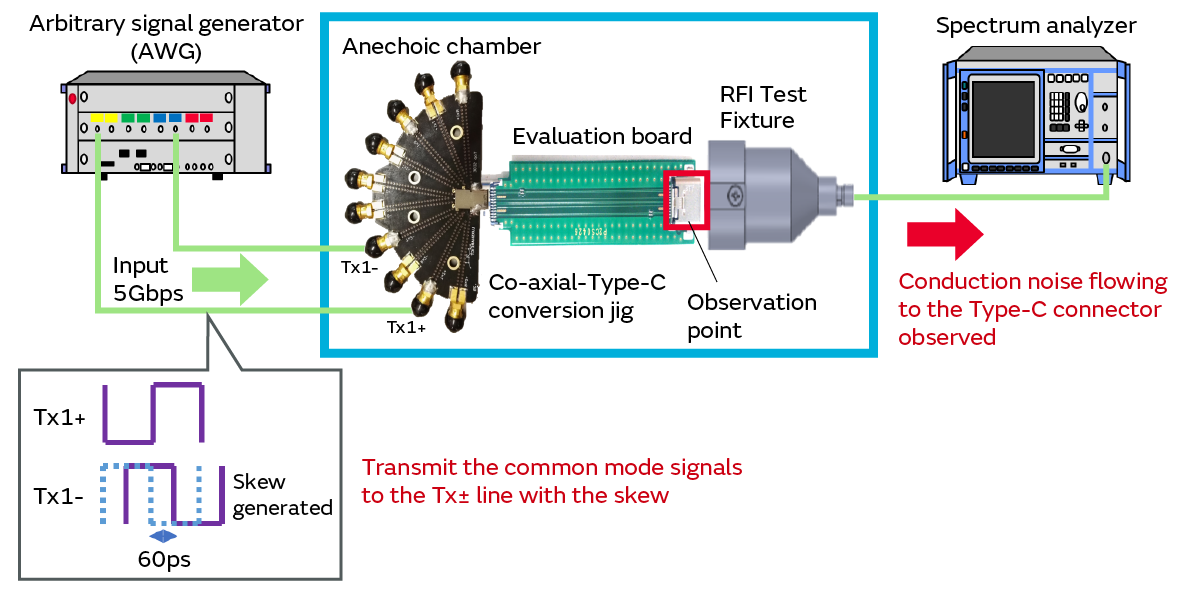
We used an evaluation board with a Type-C connector to verify the noise mechanism in an environment close to an actual device evaluation. The figure below shows that evaluation system. We input 5 Gbps signals using an arbitrary signal generator (AWG) as the signal source.
Moreover, signals from the AWG are input into the evaluation board via the coaxial-Type-C conversion jig. At this time, a skew of 60 ps is generated between the Tx± lines on the AWG to generate common mode signals.
We observed the noise conducted to the Type-C connector GND in the evaluation board under these conditions.
Next, we also confirmed the results when applying noise suppression measures such as by reinforcing the GND of the Type-C connector and equipping a common mode choke coil (CMCC) onto the Tx± line.
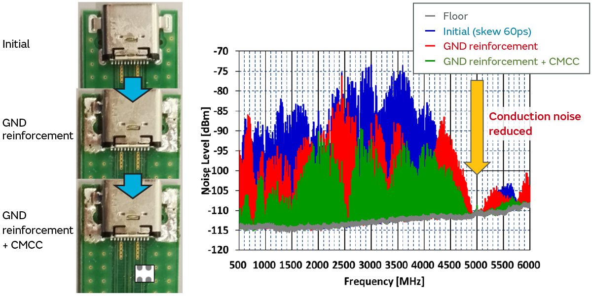
We give the evaluation results below.
The blue spectrum is the initial noise evaluation results with Skew 60ps applied. The red spectrum is the evaluation results with the GND of the Type-C connector reinforced. The green spectrum is the evaluation results with the CMCC equipped onto the Tx± line in addition.
As shown in the figure, we observed the conduction noise to the connector GND under conditions close to an actual device evaluation. Meanwhile, we took noise suppression measures and confirmed that the noise conducted to the GND of the Type-C connector was reduced.
Confirmed in the RFI test
We clarified the noise mechanism and noise suppression techniques through an investigation using an evaluation board.
Next, we applied it to an RFI test using an actual device and confirmed whether these noise suppression techniques were effective.
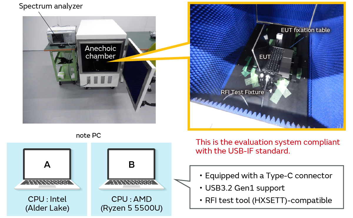
The figure shows the evaluation system. We built an evaluation system compliant with the USB-IF standard and conducted the RFI test with a laptop serving as the EUT this time. We selected two laptop models. We respectively used an Intel (Alder Lake) model and AMD (Ryzen 5 5500U) model. The selection criteria for these laptops is that they are equipped with a Type-C connector and support USB3.2 Gen1 and that they are compatible with the tool (XHSETT) necessary to output the test signals required for the RFI test.
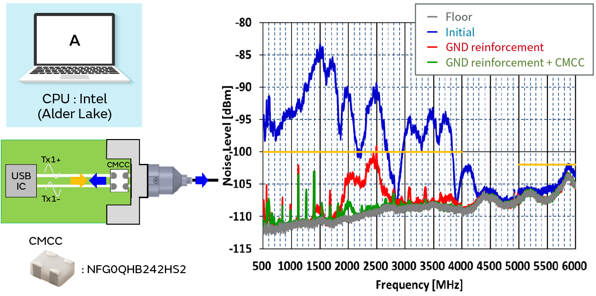
RFI Test results (model A)
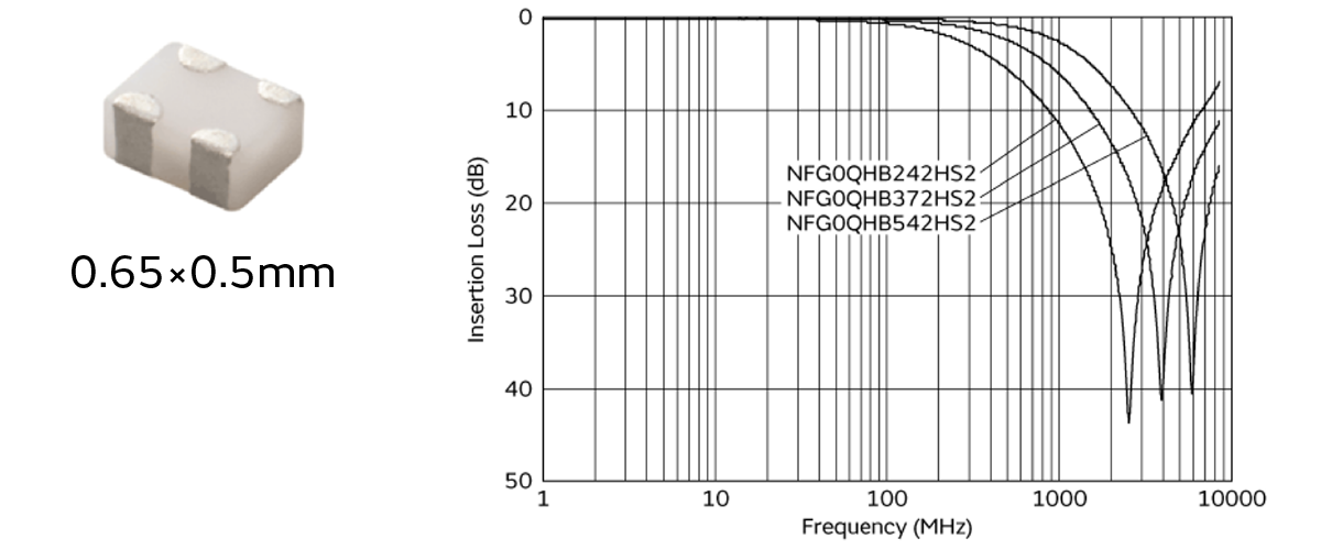
We give here the RFI test results using the Intel CPU laptop (model A). We confirmed that the initial noise before the noise suppression measures exceeded the noise limit value. In contrast to that, we obtained a noise suppression effect with a margin of at least 3 dB with respect to the noise limit value by applying the GND reinforcement and CMCC noise suppression measures. We employed a NFG0QHB242HS2 with a large suppression effect with respect to the noise frequency band for the CMCC we used.
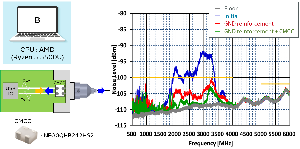
RFI Test results (model B)
Next, we give the RFI test results using the AMD CPU laptop (model B). We confirmed that the initial noise before the noise suppression measures exceeded the noise limit in the same way as with the Intel CPU model. We also obtained a noise suppression effect with a margin of at least 3 dB with respect to the noise limit value here by applying the GND reinforcement and CMCC noise suppression measures.
We obtained a similar improvement effect in these two laptop models with different board designs. Accordingly, we were able to clarify with the actual device evaluation that reinforcing the GND of the Type-C connector and equipping a CMCC are effective measures against the noise observed in the RFI test.
Noise suppression solutions to clear the RFI test
We summarize below the noise suppression solutions to clear the RFI test.
Noise suppression measure 1:
We reduce the impedance mismatch between the board GND and connector GND by reinforcing the GND of the Type-C connector.
⇒ The mode conversion due to the impedance mismatch is one of the causes of noise in conduction noise to the connector.
Noise suppression measure 2:
We suppress the common mode signals that flow onto the Tx± line by equipping a CMCC onto the Tx± line.
⇒ The signal skew possessed by the ICs and the common mode signals generated by unequal length wiring are the causes of the noise conducted to the connector.
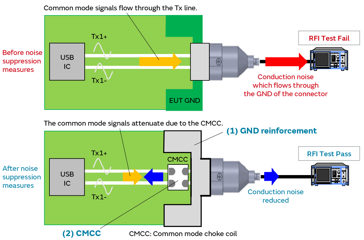
It is possible to reduce the noise in the RFI test by reinforcing the GND and equipping a CMCC.
Summary
- We observed the conduction noise that flows to the GND of the Type-C connector during USB3.2 Gen1 (5 Gbps) transmission in the RFI test measurement.
- It is possible to reduce the conduction noise that flows to the GND by reinforcing the GND and equipping a CMCC.
- We were able to reduce the noise below the limit value of the RFI test with the devices we prepared this time thanks to these noise suppression measures.
CMCC recommended to clear the RFI Test
Related articles
- Electromagnetic Interference from Industrial Equipment: Effects on Wireless Communication and Modern Mitigation Strategies
- Immunity improvement method for industrial equipment
- Murata Manufacturing Presents Solutions to Realize a Safe and Comfortable Car Society at the Automotive Engineering Exposition