Noise suppression technologies/case study introduction (Consumer)
Noise countermeasures for ameliorating sensor malfunction (3)
INDEX
Introduced here are noise countermeasure examples that represent a BCI test, which is a conduction immunity standard directed at onboard equipment.
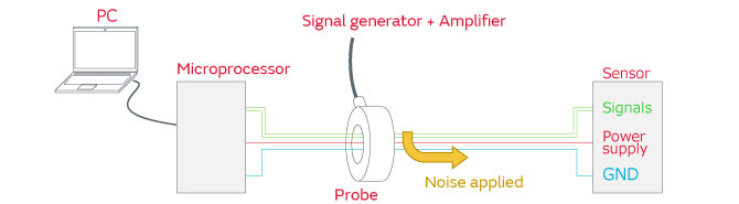
We examine the countermeasures and effectiveness by paying attention to the effects of noise on each of the power supply lines and the signal lines for conditions under which a sensor malfunction arises.
Examples of power supply line noise countermeasures
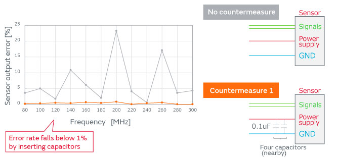
Irregularities (output errors) of the sensor output value are generated as the effect of noise on the power supply lines of the sensor. The noise level injected onto the power supply lines was kept constant and the size of the output error before and after the use of the countermeasure was examined.
Because malfunction of the sensor output value is attributable to the normal mode noise of the power supply lines, four low-ESL capacitors of 0.1 µF were inserted in the vicinity of the sensor.
This resulted in the suppression of the output error of the sensor to less than1%.
When further noise countermeasures are required, as previously mentioned, inductors and capacitors can be configured into a pi-type filter.
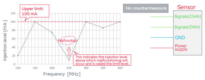
Examples of signal line noise countermeasures
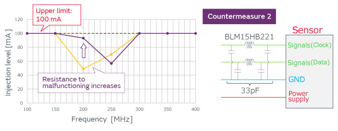
The communication of the sensor may stop due to the effect of the noise on the signal lines of the sensor. The injected noise level was increased, and the level of the limit for proper operation (at which malfunctioning did not occur) was examined.
| Initial | Resistance to malfunctioning differs greatly with frequency. (In this example, resistance is low at 100 MHz and 250 MHz.) |
|---|---|
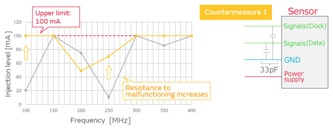
| Countermeasure 1 | Addition of capacitors improves resistance to malfunctioning at 100 MHz and 250 MHz. |
| Countermeasure 2 | A configuration of ferrite beads and capacitors improves resistance to malfunctioning at 200 MHz and 250 MHz. |
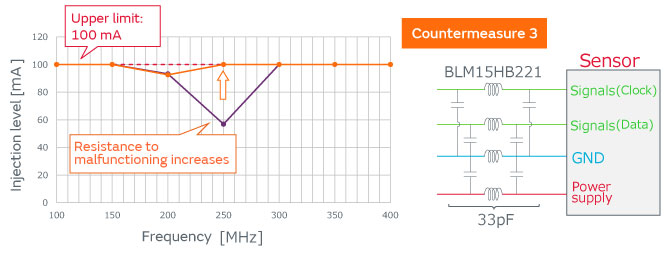
| Countermeasure 3 | To obtain a balance, a pi-type filter is configured for the power supply line and ferrite beads are also added to the ground (GND) line. This improves resistance to malfunctioning across all frequency ranges. |
By putting countermeasure 3 (recommended circuit) into practice, it was confirmed that noise resistance became favorable across the entire frequency bandwidth.
This has been an introduction to the necessity of countermeasures for the noise that affects sensors and the recommended circuits, as well as the anticipated problems that are the mechanisms of sensor malfunctioning due to noise, and examples of countermeasures.
A wide variety of products have been made available to help in the solution of your problems and for product selection.
▼ Please check the product details below ▼
| Series name | Applications | Part Number | Stock Check | Impedance (at 100MHz) |
Rated Current (at 85℃) |
DC Resistance (max.) |
|---|---|---|---|---|---|---|
| BLM15HB series |
For Consumer | BLM15HB121SN1 |  |
120Ω | 300mA | 0.7Ω |
| BLM15HB221SN1 | |
220Ω | 250mA | 1Ω | ||
| For Automotive (Infotainment) |
BLM15HB121SZ1 | |
120Ω | 300mA | 0.7Ω | |
| BLM15HB221SZ1 | |
220Ω | 250mA | 1Ω | ||
| For Automotive (Powertrain/Safety) |
BLM15HB121SH1 | |
120Ω | 300mA | 0.7Ω | |
| BLM15HB221SH1 | |
220Ω | 250mA | 1Ω |
| Series name | Applications | Part Number | Stock Check | Impedance (at 100MHz) |
Rated Current (at 85℃) |
DC Resistance (max.) |
|---|---|---|---|---|---|---|
| BLM15HD series |
For Consumer | BLM15HD601SN1 | |
600Ω | 300mA | 0.85Ω |
| BLM15HD102SN1 | |
1000Ω | 250mA | 1.25Ω | ||
| BLM15HD182SN1 | |
1800Ω | 200mA | 2.2Ω | ||
| For Automotive (Infotainment) |
BLM15HD601SZ1 | |
600Ω | 300mA | 0.85Ω | |
| BLM15HD102SZ1 | |
1000Ω | 250mA | 1.25Ω | ||
| BLM15HD182SZ1 | |
1800Ω | 200mA | 2.2Ω | ||
| For Automotive (Powertrain/Safety) |
BLM15HD601SH1 | |
600Ω | 300mA | 0.85Ω | |
| BLM15HD102SH1 | |
1000Ω | 250mA | 1.25Ω | ||
| BLM15HD182SH1 | |
1800Ω | 200mA | 2.2Ω |