NFZ2HBM

Noise suppression technologies/case study introduction (Consumer)
INDEX
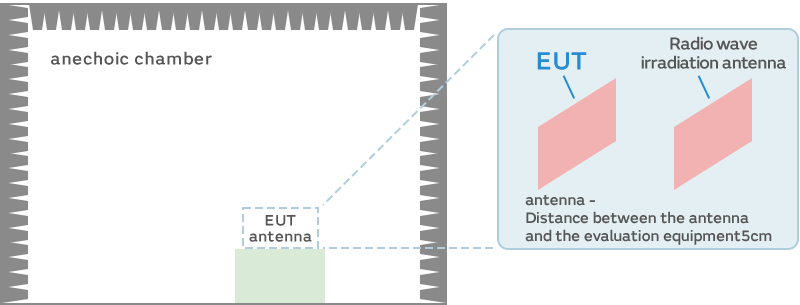
Next, we conducted a wireless communications radio wave proximity irradiation immunity test. There are no official noise standards for this test. Therefore, we built our own measurement system to conduct the test.
We radiated radio waves in 10 MHz steps for every 100 MHz in the 700 MHz to 2,600 MHz frequency band on the assumption of LTE and Wi-Fi communications radio waves to confirm whether the behavior of the motor changes according to the motor rotational speed and consumption current.
Irradiated radio wave frequency band:
We conducted an immunity evaluation in 10 MHz steps for every 100 MHz from 700 MHz to 2,600 MHz (assuming LTE and wireless LAN communications radio waves)
Irradiated electric field strength:
10 V/m or more, 5-second irradiation at every frequency, pulse modulation of 0.2 kHz and a duty of 50%
Proximity distance: 5 cm
We used a wideband sleeve antenna (model number: NKU07M32G made by NoiseKen).
We continuously operated the motor for one cycle (positive rotation: 1.5 seconds / negative rotation: 1.5 seconds).
We monitored the counter in the main IC to measure the motor rotational speed and motor consumption current.
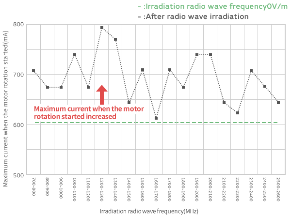
The left side of the figure below shows the motor rotational speed and current waveform when the motor is operating normally. Looking at the rotational speed, we can see that the positive rotation and reverse rotation repeat every 1.5 seconds. On the other hand, looking at the current waveform, there are characteristic changes. A large current flows (605 mA in this example) at the moment when the rotation direction of the motor switches. It then settles to a small current (100 mA) after that. The maximum value of the current at the time of this inversion increased when we conducted the immunity test. We can see that it is affected by external noise. The degree of impact of this amount of change differed depending on the frequency of the irradiated radio waves.
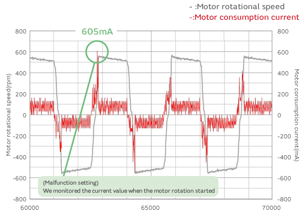
※Motor Rotational Speed and Consumption Current in the Initial State
It is assumed that this problem is generated by the following mechanism.
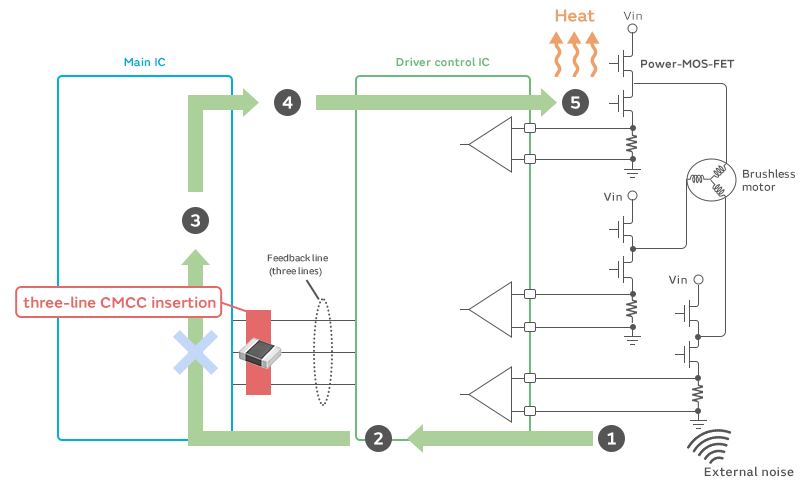
When external radio waves are irradiated as noise, the noise combines with the board wiring and other parts in common mode. The operation of the motor is controlled by the main IC mounted on the board. A feedback circuit is configured between the motor and the main IC. Accordingly, the noise combined in common mode is superimposed on the feedback signals. When the feedback signals mixed with noise are input into the main IC, some of the noise in common mode in the IC is converted to differential mode. The main IC, which has received feedback at an incorrect value as a result of it being mixed with noise, then outputs an incorrect control signal. Current greater than the amount necessary to rotate the motor flows in this case. This means the excess current is consumed as waste energy.
It is effective in such cases to remove the noise of the common mode component from the feedback signals input into the main IC. The feedback signals of a three-phase motor are configured in three lines. Therefore, we use a common mode choke coil (CMCC) with three lines combined.
The increase in the maximum current flowing to the motor significantly decreased when we conducted the same evaluation using a CMCC.
This prevents the control of the motor from being disturbed even if external noise penetrates it. In addition, excess current does not flow. Therefore, it is also possible to prevent the capacity of the battery from being unnecessarily reduced.
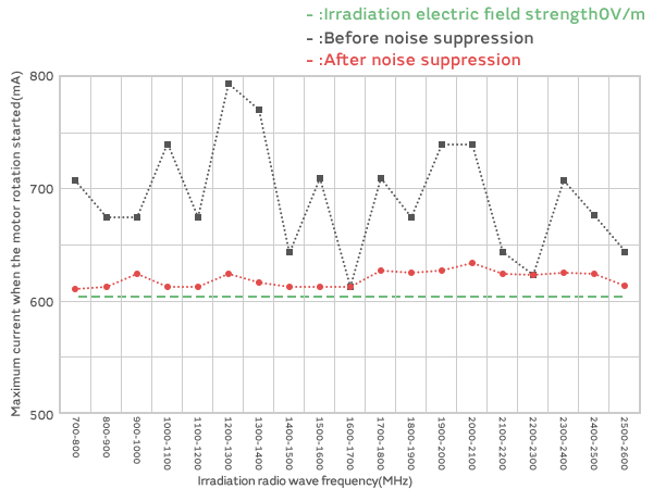
The maximum current drops by adding a three-line CMCC. It is possible to suppress main IC failures.
The life of the battery is extended, which saves energy
Service robots are used in home environments and similar settings. Accordingly, noise suppression is important. The issue caused by switching noise generated by the motor driver being radiated is attracting attention as an emission problem. In terms of immunity problems, external noise sometimes penetrates the feedback signal line of the driver, and incorrect control signals are then transmitted to the motor, causing a failure.
These are small noise filters compatible with large currents. We select a constant to match the noise frequency.
This series is compatible with large currents up to 11 A. These filters can be used at any point with a maximum operating temperature of 150°C.
We select a product to match the noise frequency.

