Capacitor
Capacitor Guide
Due to heightening concern over the global environment, hybrid electric vehicles (HEVs), electric vehicles (EVs) and other new technologies that reduce emissions and increase the fuel efficiency of gasoline engine vehicles are being introduced one after another. These technical advances are also creating the need for more compact electronic components that are compatible with higher temperatures and have high reliability.
Amidst these trends, Murata Manufacturing has commercialized the RH series of lead-type multilayer ceramic capacitors compatible to a maximum operating temperature of 150°C.
ECUs(Engine Control Unit) are increasingly used in various sensors mounted in automobiles as emissions countermeasures and to improve fuel efficiency. As a result, the available ECU installation space is becoming cramped, and various sensors as well as the capacitors that reduce the noise superimposed onto those sensors use lead-type components weld-connected in locations near the engine. This means that in the instant the engine is turned off, the temperature around these capacitors may exceed 125°C.
In addition, HEVs and EVs use increased battery current, and current detection circuits are sometimes configured by welding components directly to metal bars instead of conventional circuit boards. In this case, the capacitors used to remove noise in current detection circuits are not SMD products but instead lead-type components, and are mounted by direct welding, so compatibility with higher temperatures is demanded as currents increase.
Murata has developed a lead-type product compatible to 150°C to meet these market demands.
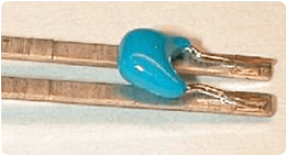
Figure 1 shows the temperature characteristics graph. The capacitance drops by approximately 30% around 150°C, but the temperature exceeds 125°C only in the instant the engine is turned off, at which time the electric circuits are not operating, so this drop in capacitance at 150°C has absolutely no effect on circuit operation. In addition, good characteristics are exhibited with almost no drop in capacitance at 5 VDC, which is the voltage of various sensors, or at the battery voltage of 13 VDC.
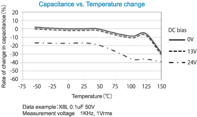
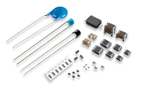
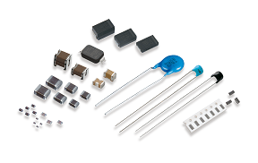
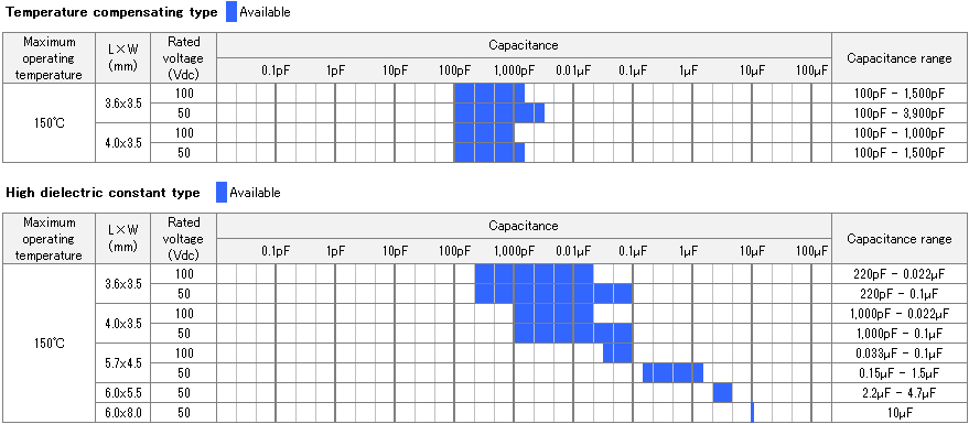
Figure 2 shows the detailed lineup.
Automotive components have a temperature cycle test requirement of 1,000 cycles between the minimum and maximum operating temperatures. Therefore, a product compatible to 150°C must satisfy a temperature cycle test of 1,000 cycles between -55°C and +150°C.
The epoxy resin generally used to coat lead-type multilayer ceramic capacitors expands and contracts greatly around the glassy-transition temperature (Tg), and as the package dimensions increase, the stress generated by this expansion and contraction also increases. As a result, cracks may occur in the coating resin during a test with 1,000 cycles between -55°C and +150°C, and if these cracks are large, the resin stress may be applied to the internal ceramic elements and cause them to crack.
The RH series uses silicon resin with little expansion and contraction to coat products with an L dimension, which is the larger of the package dimensions, of 5.7 mm and 6.0 mm. This realized products that do not experience any cracking, even after 1,000 cycles between -55°C and +150°C, which improved the temperature cycle characteristics.
The use of multilayer ceramic capacitors with good high-temperature reliability developed for automotive applications enabled satisfying the high-temperature loading test requirement of "application of 1.5 times the rated voltage for 1,000 hours at a temperature of 150°C."
In many locations where lead-type capacitors are used, the components are mounted by weld mounting instead of solder mounting onto a circuit board. The RH series was commercialized with two different types of lead wire materials (steel wire leads and copper wire leads) in accordance with the types of metals to be welded and the welding method.
The surge voltages of various types of coils may become superimposed onto power supply and signal lines.
The RH series satisfies the specifications required by the automotive surge voltage test (ISO 7637-2) (Fig. 3).
50 V rating product: Satisfies the specifications for 12 V systems
100 V rating product: Satisfies the specifications for 24 V systems
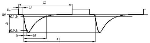
Test waveform parameters and test times
| Parameter | UA | Us | td | tr | Application times |
|---|---|---|---|---|---|
| 12 V system | 12V | -100V | 2ms | 1us | 5,000 pulses |
| 24 V system | 24V | -600V | 1ms | 3us | 5,000 pulses |
Other pulse waveform names, maximum applied voltages, and application time (or pulse application times)
| Pulse waveform | 2a | 2b | 3a | 3b | 4 | 5e |
|---|---|---|---|---|---|---|
| 12 V system | +50V | +10V | -150V | +100V | -7V | +87V |
| 24 V system | +50V | +20V | -200V | +200V | -16V | +173V |
| Application time or times | 5,000 pulses | 10 pulses | 1 hour | 1 hour | 1 pulse | 1 pulse |
See the ISO 7637-2 standard for the 2a to 5e test waveforms.
Figure 3. ISO 7637-2 pulse 1 test waveforms and required specifications
The RH series satisfies the AEC-Q200 specification generally required for automotive applications.
The ESD test of AEC-Q200 performs the electrostatic discharge test with the charging capacitor set to 150 pF, so due to the relationship [Q = CV = constant], the electrostatic voltage applied differs according to the tested capacitance. Therefore, the ESD capacity differs according to the capacitance.
Table 1 shows the ESD capacity for typical capacitance values.
Table 1. ESD proof stress for typical capacitance values
Rated voltage | Temperature | Capacitance | ||||||
|---|---|---|---|---|---|---|---|---|
- | - | 1,000pF | 4,700pF | 10nF | 47nF | 0.1μF | 0.47μF | 1μF |
100V | X8L | 2kV | 8kV | 16kV | 25kV | 25kV | 25kV | 25kV |
50V | X8L | 2kV | 8kV | 16kV | 25kV | 25kV | 25kV | 25kV |
Demands for compatibility to higher temperatures and more compact sizes are expected to intensify in the future. Murata intends to work to expand the capacitance value range, including expansion of rated voltages and investigation of film capacitors, and to actively respond to automotive market demands.
* This article is a recompilation of the contents published in the October 1, 2009 issue of High Technology by Dempa Publications, Inc.
* For details on the RH series, see the following web pages:
▼RH series web page
▼List of RH series products
* This article introduced lead-type products, but Murata also provides a lineup of SMD products compatible to 150°C.
For details on SMD products compatible to 150°C, see the following web pages:
▼GCM series multilayer ceramic capacitors for automotive applications
▼AgPd Termination Conductive Glue Mounting Chip Multilayer Ceramic Capacitors for Automotive GCG Series
The information presented in this article was current as of the date of publication. Please note that it may differ from the latest information.