Power Products


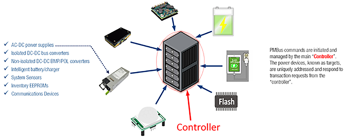
Power system developers increasingly deploy power management capability to optimize performance, uptime, and end-user experience for the complete range of any system powered by FEP PSU’s e.g.data, server, storage, industrial, and medical applications. Systems consist of a wide variety of devices, i.e.,
“targets”. Being able to control, configure, and monitor each device over a digital communication bus is required to achieve these objectives.
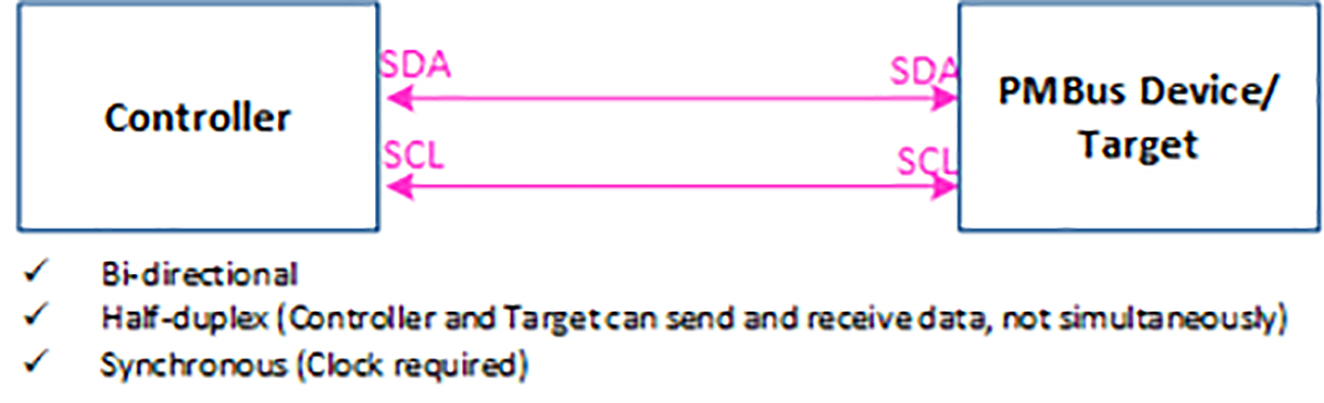
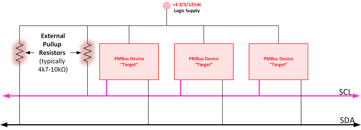
This bus needs to be easy to implement, and contain few lines, without compromising performance, as illustrated below.
In addition to the physical layer, PMBus® provides a standard command language that defines addresses and registers promoting interoperability across many types of devices. The extensive command list, also provided, includes basic command functions as well as advanced and manufacturer-defined functions ensuring flexibility across many applications, e.g.:
A wide variety of power devices and devices can be individually addressed and commanded by a single “controller” over PMBus®. For example:
PMBus® is comprised of two elements, the physical interface, defined by SMBus, and the Command language & protocol defined by PMBus, both registered trademarks of System Management Interface Forum (SMIF, Inc.).
PMBus® Member companies from across a wide range of power and other industries maintain and improve upon the protocol. This pragmatic approach results in a highly interoperable, flexible standard. Murata is a contributing member of the PMBus® committee.


PMBus® is intended to optimize the performance and flexibility of a system and is not a product or device unto itself.
Some key rules explain the separation between the PMBus® Protocol and the individual power device operation:
SMBus is compatible with I2C™ with advantages including:
PMBus® is comprised of two parts:
Defines the basic Transport requirements, hardwired signals, and addressing
Defines the Command Language
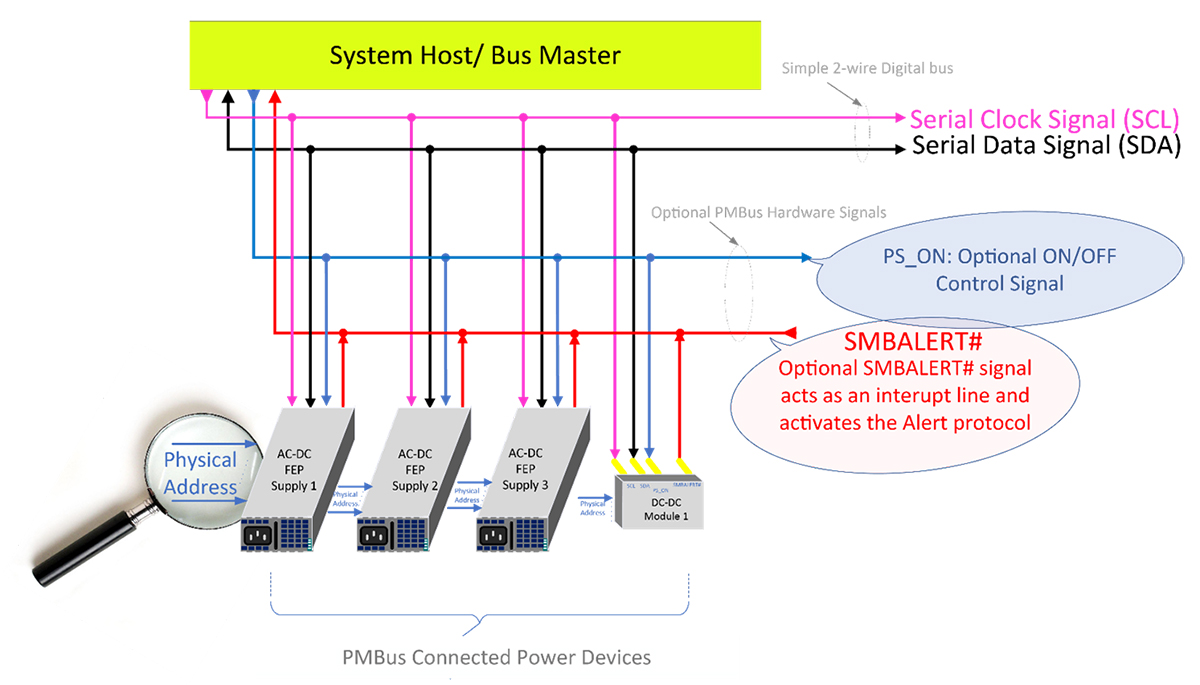
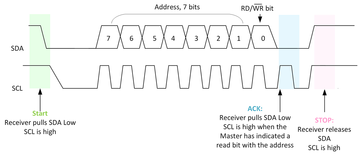
Each PMBus® Device/Target adapts a hardwired pin strapping address scheme, translated into a 7-bit address left shifted address byte. This unique address ensures “Controller” engagement occurs with the correct PMBus® Device/Target. Manufacturers adopt various address selection schemes (with trade-offs), such as:
Provides On/Off control of main output in conjunction with PMBus® control/configuration commands.
Provides real-time notice of a fault to supporting System/”Controller” by clearing immediately i.e., driven low, upon detection of a fault.
Because the system/”Controller” periodically reads the Target Devices STATUS registers (containing any set fault bit flags), this signal offers immediate notification and therefore, the maximum time for System/”Controller” to act.
SDA and SCL are Open drain/collector signals that must be externally pulled up (3V/5.0V typically).
The System Management Forum best describes the command language as:
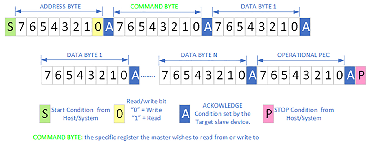
Note: When the PMBus®/Target device fails to issue an ACK after a data frame, i.e., by pulling SDA to logic low, the “Controller” detects this as a NACK.
The commands are defined within the Power Management Protocol Specification Part II – Command Language.
The command code range is from 0x00 through to 0xFF encompassing many standard, advanced, and manufacturer-defined application functions, Organized into categories:
PMBus® Defines an interoperable, easy-to-implement bus and command protocol enabling designers with configuration, control, and monitor capability.
Conventional redundancy is ubiquitous in power system deployments. It occurs when the total load current is shared by a fixed quantity of power supplies 100% of the time.
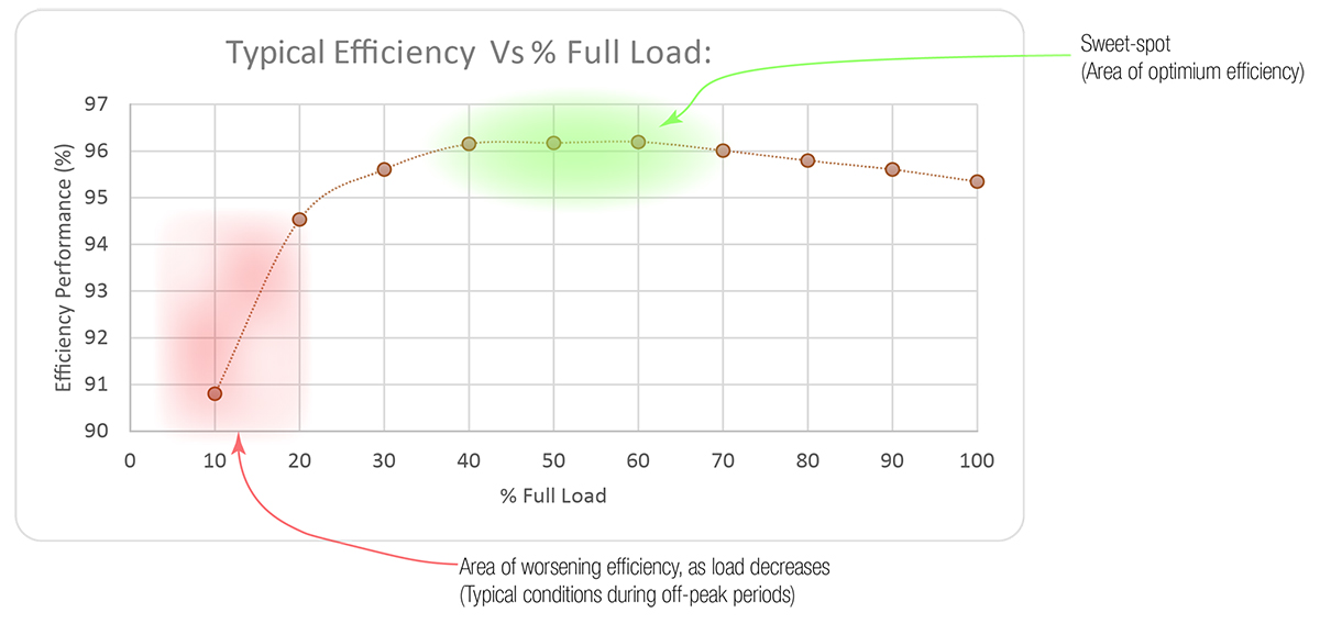
Cold Redundancy is a sharing mode established using PMBus® commands made by the system/“Controller”. Load-sharing flexibility and optimization possibilities are the aim of this feature. For example, during off-peak periods, as few as one power module sources 100% required system load current. This shifts the active power supply’s operating point efficiency closer to the green area, above, as other power supplies are shed.
The System/Controller sets each of the redundant power supplies to one of these load-sharing states:
The System/“Controller“ can utilize either of these sharing mode controls:
This signal must be interconnected to participating power supplies. It is used to force all power supplies to turn on rapidly when a fault is detected, without compromising system operation.
Power supply modules not actively delivering load must meet these criteria:
Several Murata Front End Power and DC/DC Products support PMBus®.
Developing reliable power systems optimized for performance requires advanced digital control and interconnection of the connected components. PMBus® provides a physical interface layer and command language, making power management easy to implement. The system controller can digitally command target addressable devices over PMBus® to perform an array of tasks.
Murata features PMBus® capability across many products including Front-End Power, Isolated and non-isolated Board-Mount Power, and DC-DC POL converters.
Murata Power Components home page
Murata Product example of Cold Redundancy advanced feature implementation
System Management Interface Forum (SMIF) home page
The terms “Cold redundancy”, and “Cold Redundant” originate in Intel® Corporation CRPS specifications.
PMBus® and SMBus are registered trademarks of System Management Interface Forum, Inc – All rights reserved
I2C is a trademark of NXP B.V.