
Digital Modulation - The Basics of Digital Communication
The process of taking a photo with a smartphone and sending [transmission] that photo [data] to an acquaintance who receives it [reception] is called communication. (In this example, since electricity is used, it can be referred to as electrical communication.) This article will provide a basic explanation of signals as the movement of the "data" explained in a previous article, "What Is Digital Data? The Basics of Digital Communication," as well as communication speed as the rate at which data is transmitted, and digital modulation as the operation used to deliver data over long distances.
1. Data Transmission and Reception
1.1 Data Movement and Signals
Data is a collection of symbols and codes, and is in a static state when stored in digital devices or recording media. Below, we will focus on how that data dynamically travels through transmission paths (communication paths) such as cables and space.
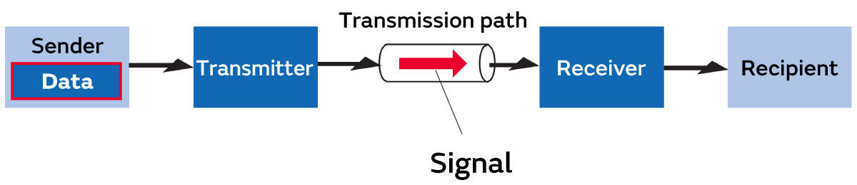
When data in this static state is processed and moves from a transmitter through a transmission path, we will refer to that data as a signal (Fig. 1). This means that when you send a photo from your smartphone to an acquaintance via the Internet, the data is sent as a signal. A signal is a time axis characteristic (although it also has the aspect of a frequency axis characteristic), but for simplicity, we will consider that "moving data in a time series creates a signal.
1.2 Speed of Data Movement
As explained in a previous article, "What Is Digital Data? The Basics of Digital Communication," units of data include bits and bytes, where a byte consists of 8 bits, and these units are used to indicate data quantities. Likewise, there are also units for signals, which are the movement of data (Fig. 2). These are known as communication speed (transmission speed), and represent the amount of data transmitted per second. There are a number of ways to refer to data speed, and the general terms are summarized in Table 1 (the terms used may vary depending on the situation).

In the signal shown in Fig. 2, the data in order of transmission is "01001101." Also, the signal level is the voltage or current, where high (H) corresponds to "1" and low (L) corresponds to "0."
This kind of waveform is referred to as a square or rectangular wave.
| Data speed | Unit | |
|---|---|---|
| Communication speed (Transmission speed) | Signal speed | bps (also bit/s, b/s) |
| Transfer speed | B/s (also byte/s, Byte/s), bps (also bit/s, b/s) | |
| Modulation speed | baud | |
The term "communication speed" is commonly used for data speed, and is frequently seen, as it is used to indicate the transmission speed in smartphone and Wi-Fi specifications, etc.
When only the unit bps (bit per second) is used, it is called the "signal speed," and when mainly the unit B/s (byte per second) is used, it is called the "transfer speed." Transfer speed uses bits, bytes, or character count depending on the amount of data transmitted*1.
*1 For example, when transmitting 100 characters each second where each character is 1 byte, the transfer speed is 100 characters per second, or 100 B/s. Since 1 byte is 8 bits, when converted to bits, the transfer speed becomes 800 bps. In this way, when the unit [B/s] is used for transfer speed, converting it to [bps] makes the transfer speed and signal speed the same.
The other unit "modulation speed" will be explained along with other characteristics such as the relationship between modulation speed and signal speed in a later article, "Increasing Communication Speeds - The Basics of Digital Communication," so it is only introduced here as a type of data speed.
2. Digital Modulation
2.1 Modulation: Technology Required for Long-Distance Data Transmission
In order to transmit data over long distances by electrical communication, an operation called "modulation" is required on the transmitting side (Fig. 3). For example, even if you shout, your voice may reach 10 or 20 meters away, but it is thought to be able to reach several tens of meters at most. However, by converting the vibration of sound into an electrical signal and imposing (modulation) it on an electrical wave (carrier wave), it can be delivered over long distances. This technology is the basic principle behind analog phones and analog radio, which are examples of applying analog modulation.

Similarly, digital data represented by "0" and "1" can also be transmitted over long distances by modulation. Thanks to this technology, photo data on a smartphone can be modulated onto radio waves and delivered to acquaintances.
2.2 Typical Examples of Digital Modulation
In order to transmit a digital raw signal (baseband signal*2) over long distances, a continuous wave (sine wave) described above as a carrier wave is required. Digital modulation consists of changing the amplitude, frequency, and/or phase of the carrier wave according to the baseband signal to generate a modulated wave. There are various types of digital modulation, with ASK, FSK, PSK, and QAM being typical methods (Table 2). The concepts and images of ASK, FSK, and PSK are described below.
(QAM is a modulation method that is an expansion of the PSK approach, so for convenience it will be explained in a later article, "Increasing Communication Speeds - The Basics of Digital Communication.")
*2 The signal when the digital data itself is moved
| Modulation method | Description |
|---|---|
| ASK (Amplitude Shift Keying) modulation | Amplitude Shift Keying modulation: Modulation where a constant amplitude carrier wave is output when the baseband signal is "1" |
| FSK (Frequency Shift Keying) modulation | Frequency Shift Keying modulation: Modulation where a high frequency is output when the baseband signal is "1" and a low frequency is output when it is "0" |
| PSK (Phase Shift Keying) modulation | Phase Shift Keying modulation: Modulation where a carrier wave with a phase difference of 0° is output when the baseband signal is "1" and a carrier wave with a phase difference of 180° is output when it is "0" |
| QAM (Quadrature Amplitude Modulation) | Quadrature Amplitude Modulation: Modulation that uses two carrier waves with a phase difference of 90°, and varies the amplitudes of those waves to output a composite carrier wave |
2.2.1 ASK (Amplitude Shift Keying)
The most basic digital modulation method is ASK. As shown in Fig. 4, "0" and "1" are expressed by varying the amplitude of the carrier wave. A modulated wave is generated with "1" where the carrier wave amplitude (voltage) is high and "0" where it is low in the same manner the baseband signal, and the amplitude changes over the same bit length as the duration of 1 bit (bit length) of the baseband signal.

*3 The unit of time variation of the modulated wave is called the symbol. In case of a binary signal that represents the binary values of "0" and "1" (1 bit) with a single modulation, the bit length and symbol length are the same.
2.2.2 FSK (Frequency Shift Keying)
As shown in Fig. 5, "0" and "1" are expressed by shifting to lower and higher frequencies based on the frequency of the carrier wave. In Fig. 5, assuming a carrier wave frequency of f, shifting to a frequency f1 that is higher than f is defined as "1" and shifting to a frequency f0 that is lower than f is defined as "0."

2.2.3 PSK (Phase Shift Keying)
"0" and "1" are expressed by shifting the phase of the carrier wave. As shown in Fig. 6, "1" and "0" can be respectively expressed by using a sine wave with phases of "0" and "π," which is the state shifted by half a cycle (180°).

Table 3 organizes the characteristics of the ASK, FSK, and PSK modulation methods introduced above. Each has advantages and disadvantages, and the choice of modulation method is determined by the purpose, application, and environment.
Modulation | Noise | Frequency | Power | Cost |
|---|---|---|---|---|
ASK | Low | Low | Low | Low |
FSK | Medium | Medium | Medium | Medium |
PSK | High | High | High | High |
*4 Noise resistance: The resistance to external noise that the modulated wave carrying the data is subject to while traveling through the transmission path (space) as shown in Fig. 7. High noise resistance means high communication quality (a small error rate of the modulated wave signal).
(Repost of Fig. 2 of "Basic Knowledge of Wireless Communication: Wireless Mechanism (1)")

*5 Frequency utilization efficiency: In this article, it is considered an indicator of how much data can be transmitted within the same frequency bandwidth per unit time. This will be explained in a separate article.
Column: What Is a Signal?
Normally, the word "signal" brings to mind a traffic signal such as used at road intersections or railways. In this article, however, it refers to data converted (modulated) to a format suitable for transmission via wireless communication. In fact, the term electrical "signal" can include mathematical representations, but it seems to currently possess multiple meanings as follows (in this article, it is used in the sense of meaning 1). Note that the signal level is voltage or current.
- Analog waveforms (e.g., sound) and digital waveforms (e.g., text and images) data as information*6 and represented as a function of time (with time on the horizontal axis)
- Time function analog waveforms (e.g., carrier waves) and digital waveforms (e.g., pulse modulation waves generated for efficient conversion from DC to DC by DC-DC converters) that have no relation to data as information*6
- Still images, which are spatial functions, and videos, which are time-space functions
*6 Information: Data that can be interpreted by humans and used to make decisions, take action, etc. (e.g., text, images, etc.)
In meanings 1 and 2, signal is indicated on the time axis, and in meaning 3, signal is indicated on the position axis. Explanation of these requires knowledge of a mathematical concept known as Fourier transform. (Fourier series and Fourier transform will be explained in a separate article.)