Inductors
Inductor Guide
Recent years have brought increasing improvements in miniaturization, multi-functionality, performance, and energy efficiency to portable devices, home appliances, automobiles, industrial equipment, and other products. This means the electronic components used in these products must continue to become smaller and thinner and meet ever-higher performance requirements.
In the power supply circuitry at the core of these products, there is a demand for inductors that are smaller, with a thinner profile, lower DC resistance, higher current capacity, and higher reliability, along with increasingly low inductance in order to achieve high-speed switching in DC-DC converter ICs. This article introduces the characteristics of Murata's Metal Alloy power inductors, which make it possible to satisfy these requirements.
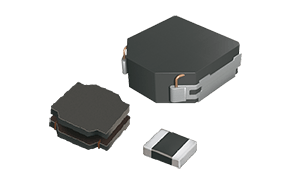
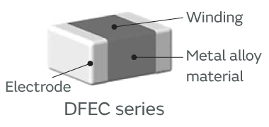
As shown in Figure 1, Metal Alloy power inductors have a very simple structure, consisting of wire windings, a metal alloy material, and electrodes, with the winding integrally molded in a metal alloy material between two terminal electrodes.
Within this simple structure, Murata has taken full advantage of its proprietary technologies in materials, winding, and molding to bring its inductors to market.
Click here for details of Metal Alloy Inductor Lineup
Metal Alloy power inductors have the following characteristics:
①Ability to handle large currents
②Moderate magnetic saturation characteristics
③Temperature characteristics independent of ambient temperature
④Low audible noise (noise in the audible frequency range)
⑤Low radiated noise
⑥Impact resistance
The remainder of this section provides more information about these characteristics and compares them to conventional ferrite products.
The general method for determining the DC superposition current value of a power inductor is to find the current at which the inductance value falls by 30%. As shown in Figure 2, despite being smaller than ferrite inductors, metal alloy inductors reach the -30% line at a higher current value than the ferrite does. This demonstrates their ability to handle large currents despite their compact size.
The reason for this difference is the higher stored energy of the metal alloy material due to its higher saturation magnetic flux density compared to the ferrite material.
The DC superposition curves in Figure 2 also reveal that the ferrite maintains its inductance value up to a certain current value, but then falls sharply once it exceeds that limit. In contrast, the metal alloy, thanks to its magnetic saturation characteristics, exhibits a more gradual decline in inductance as the current value increases from low to high.
This suggests that using a metal alloy inductor reduces the risk that the power supply circuitry will shut down or malfunction if a large current flows through it.
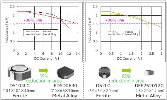
*We have discontinued or plan to discontinue the DS104LC, FDSD0630, and D52LC series.
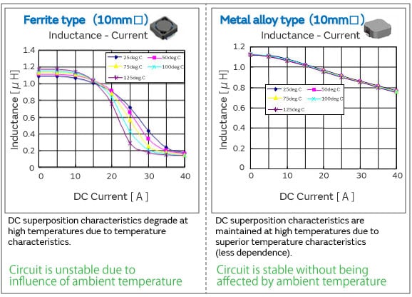
A major feature of the magnetic material used in the metal alloy is its very low variability in magnetic permeability due to ambient temperature. This means that the inductor’s DC superposition characteristics remain stable independent of the ambient temperature.
Figure 3 shows the DC superposition characteristics under different ambient temperatures for coils that share the same size and inductance value. As the figure shows, the metal alloy inductor demonstrates stable DC superposition characteristics independent of ambient temperature.
This suggests that the metal alloy inductors offer superior circuit stability (higher reliability) at high temperatures, and are better able to handle the high internal temperatures caused by the high-density mounting of components required for the miniaturization of the final assembled products.
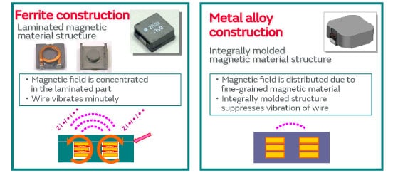
In ferrite products, when a large current flows through the coil, the large magnetic field is concentrated in the portion where the magnetic material is laminated, causing magnetorestriction (the phenomenon whereby magnetic materials become distorted by changes in their strength of magnetization) and generating minute oscillations in the winding due to the action of the magnetic lines of force between the wires.
This is known to cause an audible high-pitched squeal (so-called “coil whine”) to emanate from the coil and from the circuit board to which the vibrations are transmitted. In the case of metal alloy inductors, because the wire-wound coil is molded in a fine-grained magnetic material, there is no place where the magnetic field is concentrated. For this reason, and because any vibrations in the winding itself are restrained by the molded core, the metal alloy inductor is less susceptible to coil whine (Figure 4).
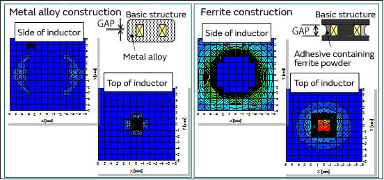
One physical property of an inductor is the way the magnetic flux around it varies over time depending on the current flow. However, it is desirable to minimize the “leakage” of magnetic flux from the inductor as much as possible. Leakage of magnetic flux causes coupling between adjacent coils and is associated with adverse effects such as fluctuations in inductance as well as adverse effects (including malfunctions) in peripheral components.
Figure 5 compares the radiated noise generated from the top and sides of coils of the same size when a constant current is passed through them. In the case of the metal alloy inductor, there is little leakage of magnetic flux from either the top or the sides.
This is due to the difference in the size of the gaps between particles of magnetic material (labeled “GAP” in the figure). In the metal alloy inductor, the tiny size of the gaps between particles keeps leakage to a minimum.
This suggests that metal alloy inductors are well suited for the high-density packaging of mounted components required for the miniaturization of the final assembled products. Furthermore, by using metal alloy inductors, designers are freed from having to take into account interference when laying out components on the board.
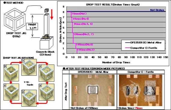
Because products such as smartphones and other portable devices are often treated roughly in actual use, the electronic components mounted inside them are required to be resistant to impact.
When a product is accidentally dropped or struck, the impact not only transmits a powerful instantaneous mechanical stress from the exterior of the product to the circuit board inside it, it also causes significant bending of the board. The components mounted on the board need to be able to withstand this bending stress as well as the impact of contact with the shield plate and casing.
Figure 6 shows the results of a comparative drop test under specific free-fall conditions.
Compared to the ferrite inductor, the metal alloy inductor, with its integrally molded structure, is more resistant to damage, because there is no single point where mechanical stress is focused.
Just as characteristic ⑤ (low radiated noise) frees designers from worrying about interference when laying out components on the board, the characteristic of impact resistance gives designers more flexibility to lay out components without worrying about where the components can be placed.
These six characteristics are the main distinctive characteristics of Murata’s Metal Alloy power inductors.
Click here to check Power Inductor Lineup include Metal Alloy Products
This article focused mainly on the key characteristics of Murata’s metal alloy products.
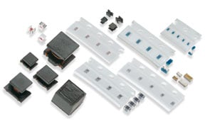
In order to be able to handle all markets and all types of assembled products, Murata’s metal alloy product lineup includes sizes from small to large.
The following issues, problems, and requirements are known to sometimes arise in the product design stage:
“There's more current, but limited space for components.”
“Because the assembled product is smaller, the internal temperature rises from the temperature of the peripheral components.”
“The design of the assembled product is complete, but the prototype exceeds the specified sound level because of a sound emanating from the area around the coils.”
“The components are packed so densely, there's no space on the board, and the components interfere with each other.”
“The components must be unbreakable to a certain extent even when the assembled product is dropped.”
Murata’s metal alloy products are well suited for problems and requirements like those above, so please give them a try!
Power inductors lineup, including the metal alloy is here
Product Engineering Section 3
Product Engineering Department
EMI Filter Division
Murata Manufacturing Co., Ltd.
The information presented in this article was current as of the date of publication. Please note that it may differ from the latest information.