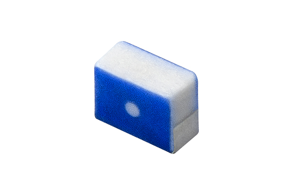
BLF02RD
Noise suppression technologies/case study introduction (Consumer)
INDEX

Recently, the popularity of wireless headsets has been growing as the number of situations where people “play sports while listening to music” increases.
Bluetooth is frequently used for communication between smartphones and headsets. However, audio can skip due to communication errors, so countermeasures are required.
This is an extremely important point of user evaluation and a difficult issue to resolve.
Here we depict an actual case to explain the interference mechanism in the device which causes the audio to skip, and key points for improvement to introduce useful countermeasures for solving the problem.
We hope that you will use it as a guide to help your design work proceed more smoothly.
We believe that there are primarily two types of design problems.
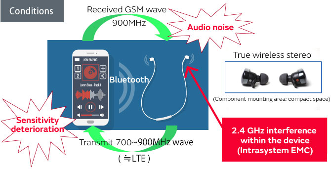
The first design problem above, interference within the headphone device, is extremely important here.
In many cases of internal headphone interference, unwanted radio waves within the device are superimposed on top of the signals required for communication, which creates noise and causes the audio to skip.
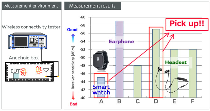
Here we used commercial products to measure the minimum reception level of a 2.4 GHz signal to verify differences in the likelihood of audio skipping due to design countermeasures to prevent interference within Bluetooth devices.
In terms of internal device interference, large graph values indicate that communication is possible even with a weak signal and the audio is unlikely to skip.
We were able to verify various levels depending on the product, but why are they so different?
We verified the reason why such differences occur using Product A, where audio skipping was frequently observed, and Product D, where that problem was not often observed.
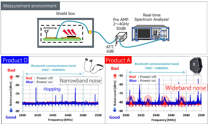
In order to know the differences between the minimum reception levels of Product A and Product D, we observed the noise spectrum received by the antenna. Signals flow through a Bluetooth antenna to communicate, but communication failures occur if noise gets into the signal flow.
The left side of Figure 3 shows Product D, which has good reception sensitivity, and the right side shows Product A, which has poor sensitivity.
The red areas on the graph show the noise level when the power supply is turned off, and the blue areas show the noise level during pairing.
Bluetooth uses frequency hopping, so the communication signals appear as a narrowband spectrum. Due to high sensitivity, the communication signals were only verified on Product D, and no other spectrum appeared.
In contrast, a spectrum with a frequency band of around several MHz was verified on Product A with its poor sensitivity. (Red colored marks)
Because Bluetooth uses hopping during communication, when this type of noise spectrum occurs across all communication frequency bands, noise mixes with the communication signal and degrades the sensitivity.
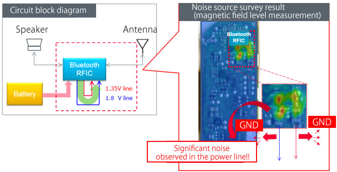
To investigate the cause of the wideband noise shown by the red marks, we measured the magnetic field distribution on the board surface of Product D. (Figure 4)
Because the noise source differs in actual noise suppression depending on the setting and situation, it is very important to identify the circuit location for effective noise reduction in advance.
The right side of Figure 4 shows the results for the magnetic field distribution strength when the frequency is fixed to 2.4 GHz. The red area represents a strong magnetic field, which indicates that the Bluetooth RF-IC with a particularly high magnetic field strength in the DC-DC converter circuit area, would be an effective location for noise suppression.
This noise is switching noise which occurs when generating power internally, and we can presume that the higher harmonics of the switching frequencies are occurring in the 2.4 GHz band.
Here we will introduce some countermeasures to deal with this problem.
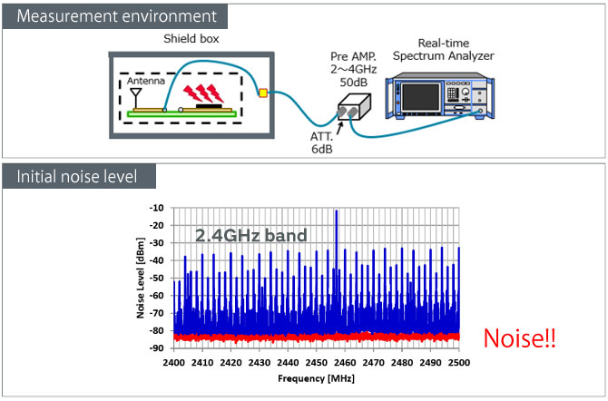
Figure 5 shows the measurement environment used to take measurements and the result of measuring noise coupled with the Bluetooth antenna.
An extremely high level of noise was observed, which requires noise suppression to reduce the level.
When implementing Bluetooth noise suppression, there are two key implementation areas.
The first area is the power supply line, and the second is the clock line.
Because the power supply line generates higher harmonics due to switching, and the higher harmonics of the clock signal extends into the 2.4 GHz band, noise is generated in the Bluetooth signal. Filtering is an effective way to suppress noise conduction.
At Murata, we have commercialized two types of filters which are designed to remove noise in the 2.4 GHz band.
The first type includes the BLF02RD and LQZ02HQ filters for power supply lines, and the second type consists of the LQZ02HQ series for clock lines.
For more details about the BLF02RD filters
For more details about the LQZ02HQ filters
The characteristics of each filter type are introduced below.
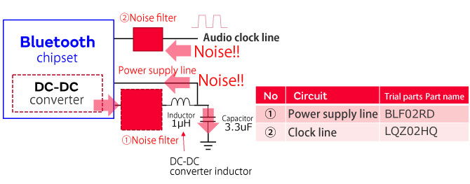
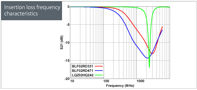
Table 1 and Figure 6 show the representative electrical specifications and insertion loss frequency characteristics of the BLF02RD and LQZ02HQ filters used for noise suppression in this instance.
In many cases, the power supply line and clock line are major sources of noise and using the appropriate filter in those circuit areas is an effective solution.
Table 1. Electrical specifications
| Part name | Stock Check |
Noise suppression target frequency |
Impedance @2.4GHz |
Rated current /DC resistance |
Feature | Target circuit |
|---|---|---|---|---|---|---|
| BLF02RD |  |
2.4GHz | 330Ω | 330mA/0.6Ω | Wideband noise response |
Power supply line |
| 470Ω | 200mA/0.9Ω | |||||
| LQZ02HQ | |
580Ω | 200mA/0.55Ω | Narrowband noise response |
Power supply line /Clock line |
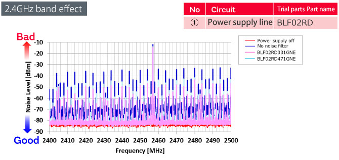
These are the results of measuring the noise spectrum coupled with the antenna during Bluetooth communication.
The BLF02RD filter was inserted into the power supply line. We were able to improve the narrowband noise by about 5 dB and verify that the BLF02RD filter is an effective solution.
For more details about the BLF02RD filters
For more details about the LQZ02HQ filters
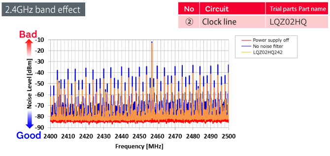
In a similar fashion, the LQZ02HQ filter was inserted into the power supply line.
We were able to verify a similar level of improvement in the narrowband noise by approximately 5 dB.
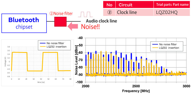
To continue, we have the waveform and noise spectrum when the LQZ02HQ filter is inserted into the clock line.
Because the LQZ02HQ filter has few low-frequency attenuation characteristics, it can remove only the problematic spectrum in the 2.4 GHz band while maintaining the signal quality.
Therefore, it is an effective way to suppress noise in a signal line such as a clock.
In this case, inserting a noise filter into the DC-DC converter circuit was effective, but the noise source may differ in some cases.
The verification method shown in the previous example is just one example, but identifying the noise source is extremely important when considering how to proceed with noise suppression.
We offer the BLF02RD/LQZ02HQ series of noise filters which are recommended for use in different circuit areas.
The BLF02RD/LQZ02HQ filters are suitable for power supply lines, and the LQZ02HQ filters are intended for clock lines.
Either series features significant attenuation in the 2.4 GHz high frequency range and can be expected to provide significant noise attenuation.
In this case, we introduced an example of noise suppression where noise within the same circuit interferes with the Bluetooth communication signal.
This technology can also be applied in non-Bluetooth devices which communicate at a frequency of 2.4 GHz, and we have implemented noise suppression components which are highly effective in the high-frequency range of 2.4 GHz in an ultra-miniature size of 0.4 mm x 0.2 mm in consideration of the need to conserve the mounting surface area when adding components.
We hope that you will utilize these components when designing measures to prevent audio skipping on a miniature scale.
For more details about the BLF02RD filters
For more details about the LQZ02HQ filters