Chip inductors for PoC LQW21FT_0H series
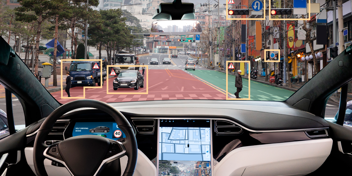
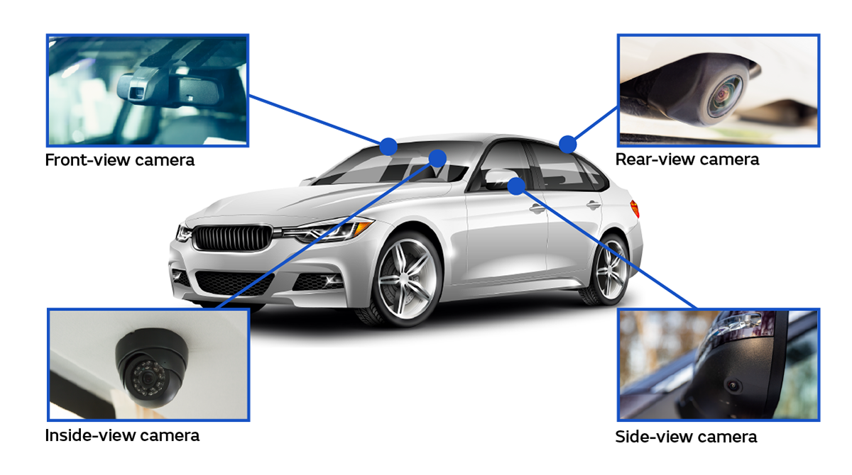
In recent years, it has become routine for cars equipped with multiple automotive cameras to be introduced to the market (Figure 1). Self-driving vehicles are equipped with numerous automotive cameras for external environment recognition.
There are several remaining technical issues that should be solved in preparation for the increase in the number of automotive cameras equipped in vehicles. One such issue is reducing the number of cables connected to cameras. Because automotive cameras are electronic devices, they must be connected to a power supply line. In addition, they also require signal lines to send captured video data to the control computer (ECU)*1. If you connect these two types of cables to each camera, the inside of the car will become a nest of cables as a result of the increase in the number of equipped cameras. The increase in cables hinders weight-saving in cars and leads to a deterioration in fuel economy.
*1 ECU (Electronic Control Unit) refers to a computer that controls automotive devices. Car models equipped with more than 100 ECUs per vehicle have already appeared, and that number is increasing along with the growing sophistication of automotive device control.
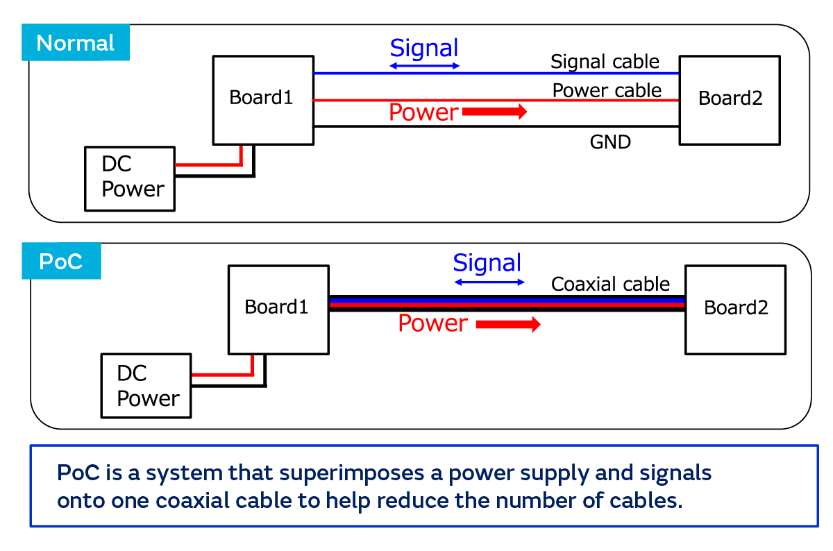
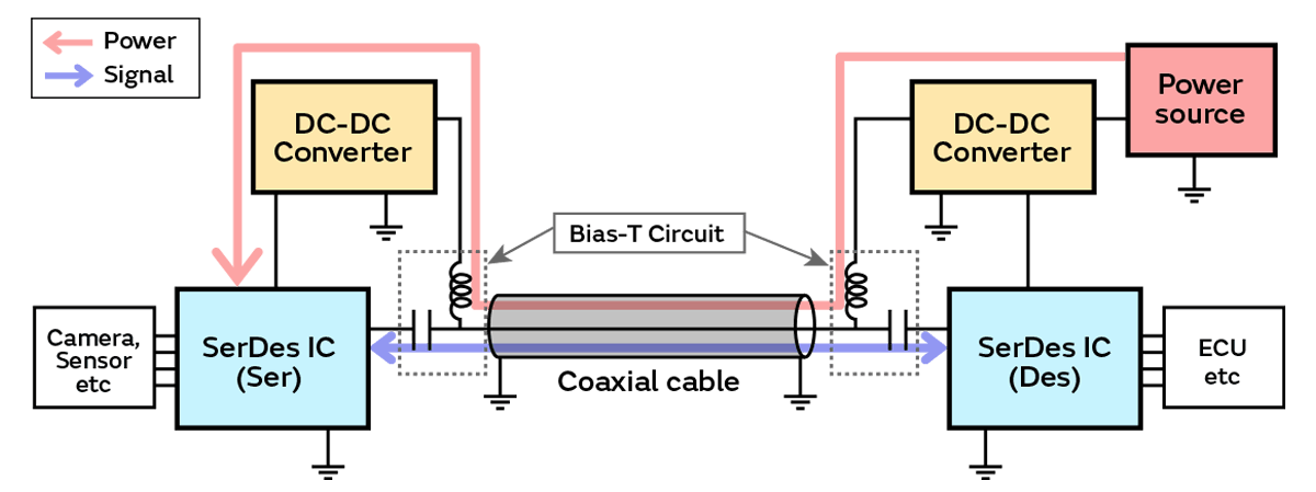
To reduce the number of cables connected to automotive cameras, many OEM*2 and Tier 1*3 manufacturers are paying attention to and actively adopting “PoC” (Power Over Coaxial), which is a technology that integrates signal lines and power supply lines (Figure 2). Currently, a digital interface called SerDes (Serializer/Deserializer) is often used when transmitting video data from automotive cameras to convert the parallel signals output by the imaging sensors to serial signals and transmit them as high-frequency signals. As introduced in the article titled “Murata’s Vehicle-mounted Inductor Products for Supporting Advancements in Vehicle-mounted Networks Through Timely and Appropriate Product Development (Parts 1 and 2),” with PoC you can apply a DC power source to image signals and control signals that are compatible with SerDes and send them over one coaxial cable.
*2 OEM (Original Equipment Manufacturer or Original Equipment Manufacturing) refers to manufacturers that produce products under the outsourcing company’s brand or the practice of such manufacturing.
*3 Tier 1 refers to companies in the automobile industry that directly supply components that they manufactured and developed to completed car manufacturers. Furthermore, companies that supply components to Tier 1 companies are called Tier 2 companies.
When introducing PoC, a circuit called a “Bias-T circuit” must be embedded on both the sides that send and receive the signals and the power supply (Figure 3). A Bias-T circuit is for separating the SerDes signal transmitted in the high-frequency band from the DC power supply (on the low-frequency side). The circuit is composed of an inductor that blocks the high-frequency video signals and a capacitor that blocks the DC power supply.
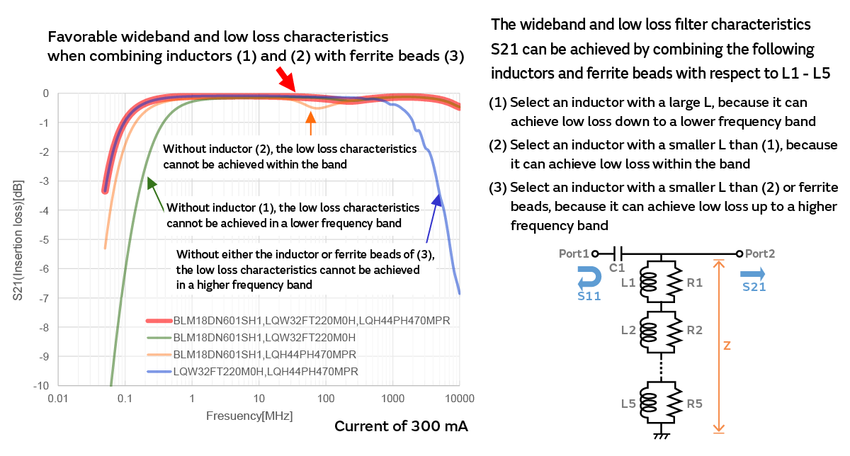
When designing a Bias-T circuit, you must select an inductor with characteristics that can precisely separate the signals and the power supply. If the inductor is not able to sufficiently separate the two, the high-frequency signals may flow into the power supply circuit, trigger power supply fluctuations, and cause devices to malfunction. In adopting an inductor, you must choose one that functions as a high-impedance filter across a wide band (several MHz to several GHz). However, it is difficult to cover a wide band with one inductor, and the required characteristics are normally satisfied by combining multiple inductors and ferrite beads (Figure 4).
The work to select the optimal combination from among a wide variety of inductor products requires unexpectedly significant effort and a lot of time. First, it is necessary to choose components according to the frequencies of the transmitted signals, the amperage of the supplied power, the ambient temperature of the usage environment, and other conditions. At that time, a determination cannot be made by simply adding together the characteristics of each individual component. That is because the parasitic capacitance*4 that occurs on the circuit board where the circuit is mounted, the parasitic inductance*5, the length and characteristics of the coaxial cable that connects to the circuit board also significantly affect the behavior in the high-frequency band. Therefore, when selecting components to adopt, it is necessary to consider the specifications of the automotive camera system to design and the characteristics of the circuit board that the circuit will be mounted on and verify the operation through simulation while trying combinations of various components to discover the optimal solution.
*4 Parasitic capacitance refers to electric capacitance unintended by the designers that occurs when wiring on a circuit board behaves like a capacitor. It is also called “stray capacitance.” The magnitude is determined by the positional relationship and shape of the wiring pattern as well as the circuit board materials, etc. Normally, it does not have a significant effect on the behavior of a low-frequency circuit, but it may cause a malfunction in a high-frequency circuit. Parasitic capacitance is generally not drawn on a circuit diagram, etc. Therefore, if a circuit malfunctions after prototyping, the effects of parasitic capacitance must be carefully investigated and analyzed.
*5 Parasitic inductance refers to inductance unintended by the designers that occurs when wiring on a circuit board behaves like an inductor (coil). It is also called “stray inductance.” It is similar to parasitic capacitance in that it is determined by the positional relationship and shape of the wiring pattern as well as the circuit board materials, etc. and by the fact that it can cause a malfunction in a high-frequency circuit.
To reduce the component selection workload, Murata Manufacturing (hereinafter, “Murata”) developed the “Bias-T Inductor Selection Tool”*6 (hereinafter, “BIST”) to support the selection of the optimal inductors to embed in a Bias-T circuit, and the tool was released for free on its website in May 2020. By configuring the minimum number of conditions, the tool discovers and presents the optimal combination of components from among the inductors and ferrite beads manufactured by Murata. Using BIST significantly reduces the effort and time required for component selection and enables selection of the appropriate components even without specialized knowledge.
*6 The Bias-T Inductor Selection Tool can be used in our SimSurfing design support tool.
When introducing PoC to be able to connect to automotive cameras with one coaxial cable, it is necessary to design a Bias-T circuit that can properly separate the signals and the power supply. However, the inductors used in such a circuit are not so easy to select. Using the BIST tool developed by Murata, anyone can easily select the appropriate components. Therefore, we spoke with the managers who were involved in the development of BIST about the incorporated features and the objectives in releasing the tool.
--The utilization of PoC in automotive cameras is attracting attention. Please tell us about the adoption situation of this technology.
Many OEMs and Tier 1 manufacturers are already adopting PoC, and cars that introduced automotive camera systems employing PoC starting several years ago are being released to market.
--What types of standards should be observed in the Bias-T circuits that are essential to PoC?
IC manufacturers that are developing and offering PoC-compliant SerDes interface chips are defining the signal line permeation characteristics (S21) and reflection characteristics (S11) for the stable operation of their own manufactured chips, S21/S11, and other standards. In addition, some OEMs establish their own standards, which are more stringent than those defined by IC manufacturers, that Tier 1 manufacturers are required to satisfy. When selecting the components that make up a Bias-T circuit, the components must be selected while also keeping such unique standards in mind.
--What points should people pay attention to in component selection?
To select components that will reliably function as a Bias-T circuit, one must consider the many phenomena that occur within the circuit. First, anti-resonance*7 occurs when multiple inductors are connected in series to create a wideband filter. To suppress the anti-resonance, resistance must be added in parallel with the inductors, but characteristics other than those involved with the anti-resonance points will deteriorate. Therefore, components with the appropriate resistance values must be selected in order to obtain the target filter characteristics. In addition, anti-resonance also manifests due to the effects of parasitic capacitance, which occurs between the inductors and the inner packaging of the circuit board. The Bias-T circuit characteristics change depending on the type of circuit board and the mounting layout. In highly precise component selection, one must consider the parasitic capacitance of each individual component and suppress the anti-resonance while selecting components that can minimize the number of components.
*7 The phenomenon in which the impedance (resistance with respect to the alternating current) becomes extremely high due to the inductance of the inductor and the parasitic capacitance that occurs in the inductor itself and between the inductor and the circuit board together with the increase of the frequency is called “anti-resonance.” When this phenomenon occurs in PoC, there is a risk that it will become unable to supply a stable source of power.
--What was the inspiration behind the development of the BIST tool for supporting the selection of components that make up a Bias-T circuit?
In anticipation of the growth of PoC applications, Murata proposed inductors that were suitable to the various automotive camera systems being developed by customers. However, it took the engineers 3 to 5 days from the time when they received the proposal request to when they were finished making the component selection. While they were able to handle the low number of proposals in the beginning, naturally they became unable to handle the work as the number of requests increased. In response, we came up with the idea of creating a tool that encapsulates the component selection know-how possessed by our in-house engineers to enable anyone to select the appropriate components.
--Initially, it was anticipated that the tool would be used internally. Why did you decide to publicly release it?
We thought that our customers were probably also struggling with component selection just like Murata’s internal personnel. We developed BIST on the presumption that it would be publicly released and aimed for a tool that would be easy to use even by someone lacking specialized knowledge.
--What aspects did you focus on to improve the ease of use?
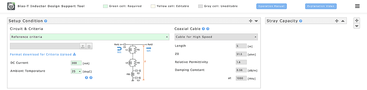
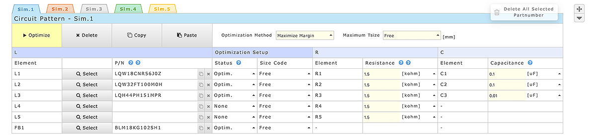
We emphasized the ability to find the optimal combination of inductors with minimal entry items. With the BIST tool that we developed, if you specify the frequency of the video data signal as well as the current value of the DC power supply and the temperature of the usage environment, it can present the optimal combination of inductors with one click (Figure 5).
In addition, we were also very particular about instantaneously finding and presenting the optimal solution after the information was entered. More than 10 billion Bias-T circuits must be calculated when the combinations of inductor products possessed by Murata are examined in a brute-force manner, and the optimal solution cannot possibly be obtained within a realistic span of time. In response, we developed an algorithm that incorporates the component selection know-how possessed by Murata engineers and established a method that handles a massive volume of product data at high speed to produce an answer in about one second.
--Can information about the circuit board that is actually being used be considered when selecting components on the customer side?
Yes, such information can be used. To begin with, a file concerning any special standards (S21, S11, etc.) is uploaded to enable the selection of components suited to those standards. Moreover, when it comes to the circuit board information, the characteristics of the Murata evaluation circuit board are initially entered. However, the optimal components are selected in consideration of the stray capacitance, etc. on the circuit board by entering information about the customer’s circuit board. Using these functions enables component selection with an even higher precision. Conversely, they can be applied to examining the factors behind the differences between the characteristics calculated by BIST and the characteristics of the actual circuit board by changing the circuit board information.
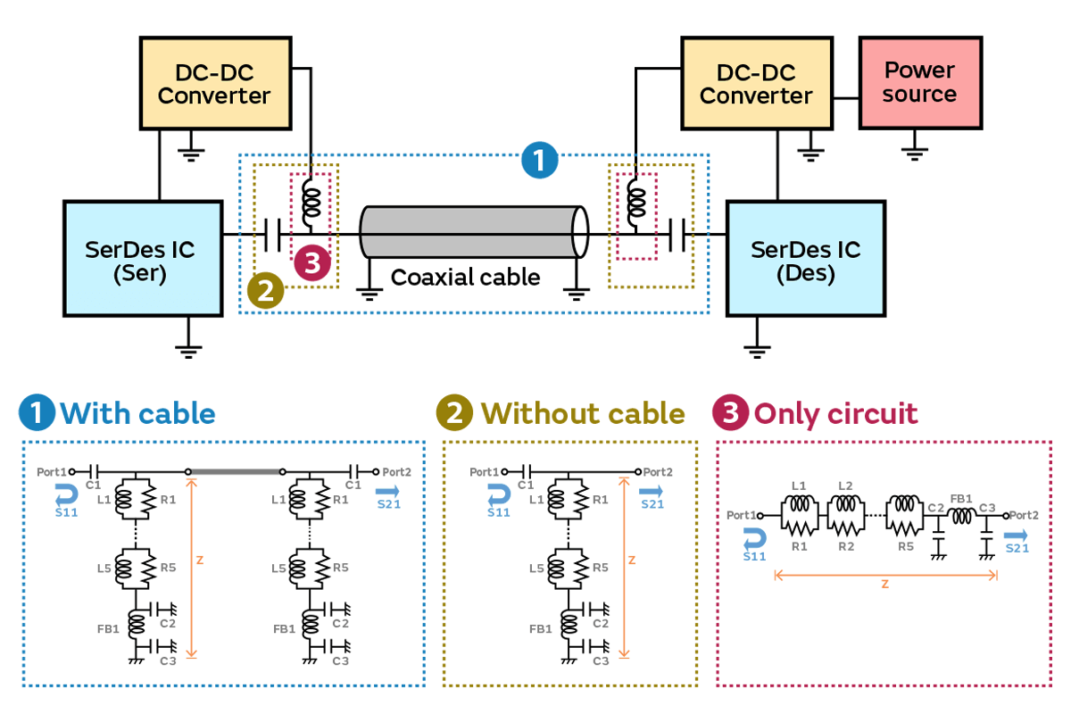
Incidentally, the simulation that is run during the component selection can cover three different types of circuits: (1) Bias-T circuits with a cable, (2) Bias-T circuits without a cable, and (3) circuits with only inductors (Figure 6).
--What kinds of information can be obtained as BIST output?
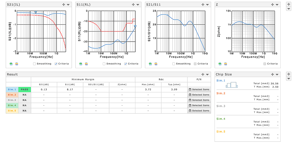
It presents the combination of inductors and ferrite beads that can obtain the best characteristics across a wide band (Figure 7). Because the miniaturization of automotive cameras has been advancing in recent years, it can also discover not only the combination with the best characteristics but also that which minimizes the mounting area on the camera side and takes up the largest margin on the ECU side.
In addition, you can also obtain a comparison of the required characteristics (S21/S11) and the frequency characteristics of the selected components, the number of components, the mounting area of the selected components, total resistance value, and other information (Figure 8). We have also made it possible to download the S parameters of the output data and SPICE circuit files, etc. as data that the user can use in their own simulations.
--How much room does BIST have to evolve and develop going forward?
We would like to expand the coverage to include PoC utilized in industrial electricity related applications that handle power with a higher voltage. SerDes-based PoE*8 is also used for machine vision employed in quality inspections, etc. on factory production lines. The component selection issues in the design of camera systems for fields such as this are similar to those in the automotive field, and BIST is an effective solution.
*8 PoE is an abbreviation of Power over Ethernet. PoE is a technology that can simultaneously transmit data and supply power to electronic devices with one Ethernet cable (LAN cable). It is widely applied to surveillance cameras, routers, and IP telephones, etc. It has been standardized under the specifications “IEEE802.3af” to supply a maximum of 15.4 W of power, “IEEE802.3at” (also called PoE+) to supply 30 W, and “IEEE802.3bt” (also called PoE++) to supply 90 W.
In addition, it can currently optimize according to the combination with the best characteristics or the combination that reduces the number of components, but we hope to diversify the optimization approaches. We are already receiving requests from customers saying that they wish to know the combination of components with the lowest price.
Going forward, the utilization of advanced camera systems will likely become more active in automobiles, of course, but also in industrial devices and many other fields being driven by digital transformation (DX). The fields of PoC application will increasingly expand, and the importance of BIST as a tool that can reduce the load when selecting the components that make up a Bias-T circuit will continue to increase. The number of system developers who lack the knowledge and skills to carefully consider the phenomena that occur in Bias-T circuits will likely increase due to the increase in the number of component selection cases. In addition, more sophisticated judgment may be required as the specifications of application systems become more diverse and the perspectives during selection become more multifaceted.
However, making the appropriate component selection is work that is essential for designing highly reliable Bias-T circuits, but that in itself cannot be described as high value-added work. BIST has become such an essential tool within Murata that some engineers have said, “The idea of selecting PoC components without using BIST is no longer conceivable.” It is a tool that we hope will be used by many of our customers who are developing systems utilizing PoC.