NFZ2HBM

Noise suppression technologies/case study introduction (Consumer)
INDEX
We confirmed the current situation for both emission and immunity problems and then examined noise suppression methods to address these problems.
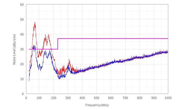
First, we confirmed the situation of emission noise. We measured the radiation noise in a commercially available service robot.
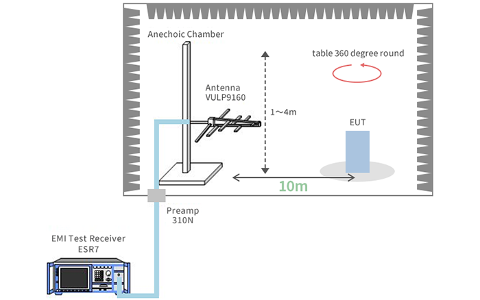
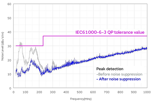
We confirmed that the noise exceeds the standard value for IEC61000-6-3 in the 30 MHz to 200 MHz band. Noise in this band is often a problem for most service robots.
We examined the noise source and transmission path.
The equipment we evaluated this time employs a brushless motor. Driver circuits are used to drive brushless motors. Three-phase PWM control circuits are commonly used as the driver circuits of brushless motors. Two switching elements per phase – six in total – are used in this control circuit. These elements generate switching noise. This switching noise is transmitted to the cable. However, the cables used in robots are often unshielded insulation-coated cables. Therefore, noise is radiated from the cable to the outside. Noise is also transmitted to the coil inside the motor. Accordingly, noise is radiated from the body of the motor.
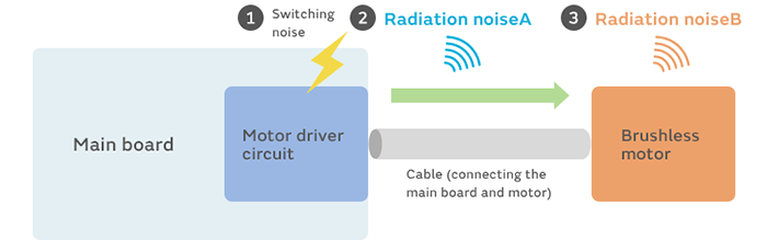
Switching noise generated in the motor driver circuit is transmitted to the cable. It is then radiated from the cable or the body of the motor. We can thus see that it is best to prevent transmission of switching noise to the cable.
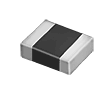
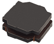
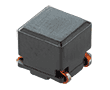
To that end, we insert a noise filter near the connector of the cable. The noise frequency is in the 30 MHz to 200 MHz (300 MHz in some cases) band. Accordingly, we select a part that is effective in this frequency band. The NFZ series (e.g., NFZ2HBM, NFZ32BW and NFZ5BBW) and the BLT5BPT series are suitable. If the motor locks for some reason, a momentary spike current may flow. This means it is best to select a part with a rated current three to five times that of the regular current. We used the NFZ2HBM this time.
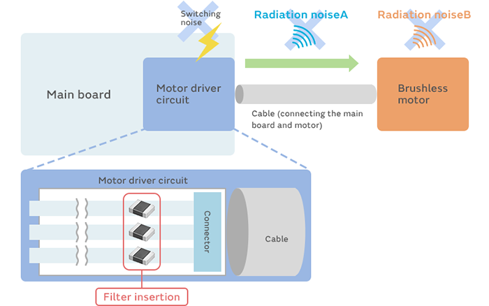
These are small noise filters compatible with large currents. We select a constant to match the noise frequency.
This series is compatible with large currents up to 11 A. These filters can be used at any point with a maximum operating temperature of 150°C.
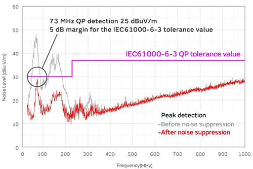
We were able to suppress the noise to the standard value or below and to secure a margin of at least 5 dB when we installed a NFZ2HBM4R4SN10 near the connector to which the cable is mounted.
These are small noise filters compatible with large currents. We select a constant to match the noise frequency.

