NFG0NCN162HL3
Noise suppression technologies/case study introduction (Consumer)
INDEX
Smartphone displays are becoming larger with higher resolutions as the volume of information handled increases. As a result, the data volume of the video signals sent to displays is also increasing.
A differential transfer interface called MIPI D-PHY has been used to efficiently transfer these signals, but use of MIPI C-PHY is increasing recently as an interface that can transfer data at even higher speeds. The MIPI C-PHY transfer system differs from that of the previous one, D-PHY, so different noise filters are needed than before.
This article describes the noteworthy features of MIPI C-PHY noise suppression and the noise suppression products commercialized for MIPI C-PHY.
MIPI C-PHY is a standard for data transfer inside mobile equipment, established by the standards organization MIPI Alliance.
Whereas D-PHY has a maximum speed of 2.5 Gbps per lane, C-PHY increases the signal speed to 5.7 Gbps.
The M-PHY standard has also been created as a successor to D-PHY, but the C-PHY standard has been created as a bridge standard between D-PHY and M-PHY. D-PHY uses typical differential transfer lines comprising two pins per lane, but C-PHY uses more complex differential transfer lines comprising three pins per lane.
| D-PHY ver1.2 | Item | C-PHY ver1.0 |
|---|---|---|
| 2pins | Number of pins/lane | 3pins |
| 4pins (Data: 1 lane, Clock: 1 lane) |
Minimum number of operation pins | 3pins(1 lane) |
| High Speed(HS)mode Low Power(LP)mode |
Mode | High Speed(HS)mode Low Power(LP)mode |
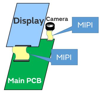
| Camera line Display line |
Anticipated locations of use | Camera line Display line |
| 80Mbps~2.5Gbps | Transfer speed/lane(HS) | 183Mbps~5.7Gbps (80M~2.5Gsym/s) |
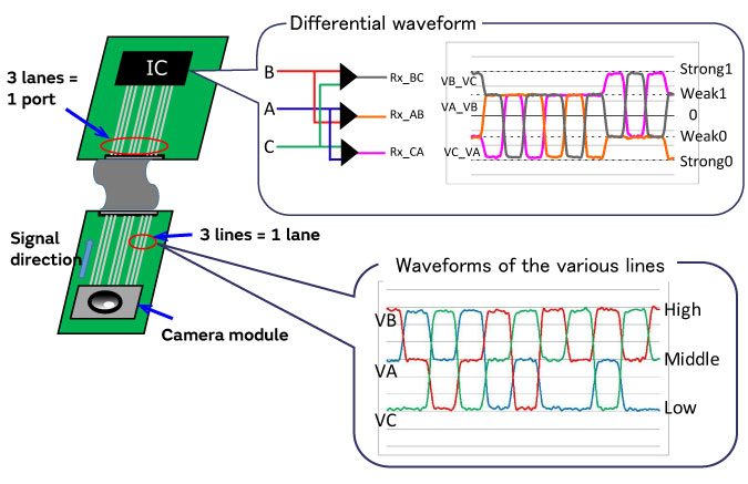
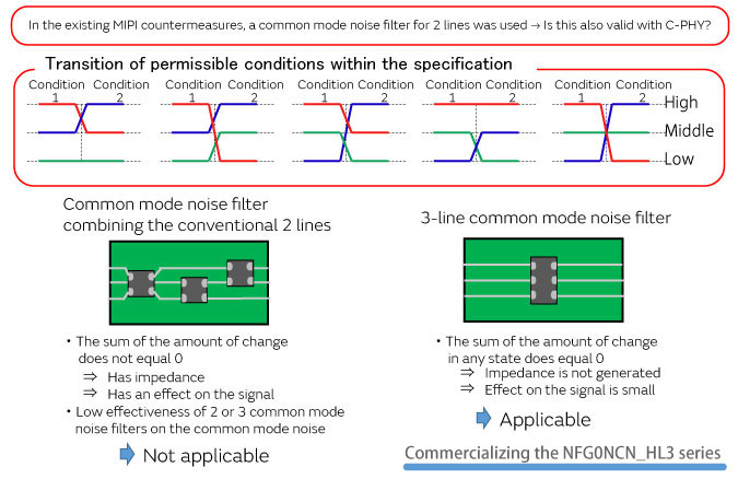
In conventional MIPI D-PHY it is necessary to remove common mode noise to avoid having an adverse effect on the differential signals, so 2-line common mode noise filters are used. However, MIPI C-PHY transmits differential signals using three signal lines, so normal common mode noise filters cannot be used as is.
One possible method is to combine three common mode noise filters as shown in the figure left below, but this has a large effect on the signals, so sufficient common mode noise suppression effects cannot be expected. Therefore, MIPI C-PHY noise suppression requires a common mode noise filter that supports 3-line differential signals.
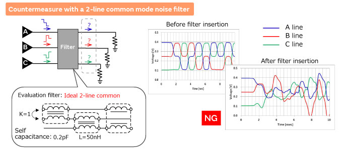
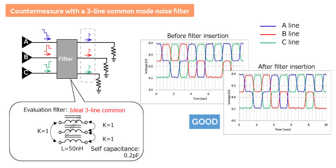
When using a 3-line common mode noise filter that magnetically couples the 3 lines internally, circuit simulation was used to check whether the signals could be transferred effectively.
Using a 2-line filter, the transfer waveform was disturbed; however, when a 3-line common mode noise filter was used, we found that the signals were transferred without disturbance to the waveform.
— Comparison of 2-line and 3-line common mode noise filters —
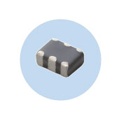
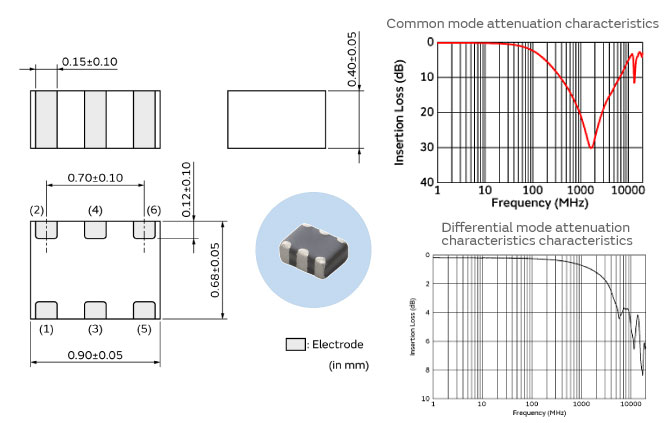
The NFG0NCN_HL3 series are noise filters that were developed as a countermeasure for common mode noise in MIPI C-PHY.
Within the miniature size of 0.90 x 0.68 mm, 3 lines are magnetically coupled in the configuration of these common mode noise filters.
NFG0NCN162HL3 has a insertion loss peak between 900MHz and 3GHz. This feature make it suitable to prevent noise interference to carrier frequency.
These filters are of a 3-line configuration for use with MIPI C-PHY.
| Product number | Stock Check |
Common mode impedance (at 100MHz) |
Amount of common mode attenuation(Typ.) | Rated current |
Rated voltage |
||
|---|---|---|---|---|---|---|---|
| 800MHz | 1GHz | 1.6GHz | |||||
| NFG0NCN162HL3 |  |
25Ω±25% | 19dB | 22dB | 29dB | 100mA | 5Vdc |
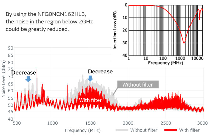
The NFG0NCN_HL3 series was used to check the effectiveness of the noise countermeasures.
The chart below compares the noise spectrum radiating from the transfer lines before and after filter insertion.
By inserting the NFG0NCN162HL3, the conspicuous noise below 2 GHz could be greatly reduced.
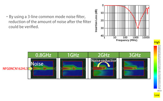
Next, a near magnetic field probe was used to observe the degree to which the noise distribution on the PCB would change.
In the locations after the filter insertion portion, the distribution of the noise was reduced, and especially the amount of 0.8 GHz or 1 GHz noise reduction was remarkable.
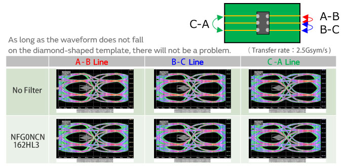
Noise countermeasure effectiveness was checked for the NFG0NCN_HL3 series of common mode noise filters for MIPI C-PHY.
By inserting the NFG0NCN_HL3 series into the signal lines, we checked whether this had an adverse influence on the signal waveform. We confirmed that for the eye pattern of the signal satisfied the specifications of the template.
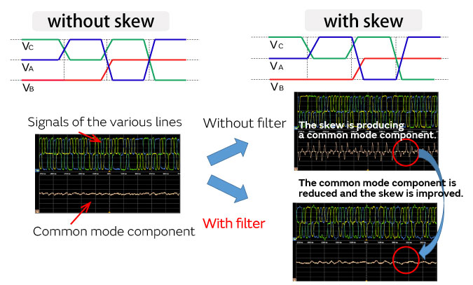
Common mode noise filters are also effective in improving the skew of differential signal lines.
Skew refers to the shift of the signal propagation time between multiple signal lines. Skew is generated by the asymmetric quality of the circuits and other factors, and this shifting of the respective signals leads to changes of the signal potential difference received at the receiving side which reduces the operating margin of the circuits.
Using a common mode filter in a differential signal circuit that has skew will remove the common mode component that was produced by the skew, and the skew will be improved. An example of skew improvement by common mode noise filters is shown below.
The use of common mode noise filters can be expected to be effective in improving the skew of transfer signals.
Since the skew (time lag between signals) is propagated by common mode, use of common mode noise filters can improve the skew.