Noise Suppression Products / EMI Suppression Filters / ESD Protection Devices
Noise Suppression Filter Guide
Recent laptop PCs have become extremely slim. When laptop PCs first appeared, they looked like super-large lunchboxes, and seemed to have more connectors than necessary.
Printer connections also used the Centronics interface, but using a thick and heavy cable to communicate with a printer at 2 Mbps is becoming a distant memory.
Currently, various equipment such as a printer, HDD, and mouse can be connected easily using thin USB cables. Furthermore, USB3.0 also provides the very reasonable communication speed of 5 Gbps (5120 Mbps).
This technology is supported by high-speed differential transmission technology.
This article provides a brief introduction to the background behind the adoption of high-speed differential transmission technology.
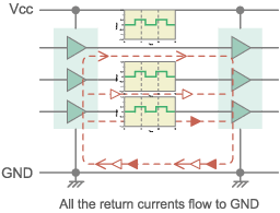
Formerly, signal transmission by cables connected to a PC mainly used the single-ended system, such as the Centronics interface used for printer connection or RS-232C used for modems. The single-ended system has multiple signal lines and a common ground (GND) that the signals return to. When detecting the voltage, the logic is determined by the signal potential relative to GND. With this system there are the following two methods of increasing the transfer rate:
(1) Increase the transfer speed of each signal line; and
(2) Increase the number of signal lines.
Method (2) would result in an even larger connector and thicker cable. However, reducing the number of signal lines and making the connector and cable slimmer are desired even more than increasing the signal transmission speed.
Conversely, simply increasing the signal speed requires expensive ICs, and also increases the radiated EMI noise.
Reducing the voltage amplitude shortens the signal rise and fall times, which facilitates high-speed transmission. However, there are also drawbacks, as lowering the voltage makes it easier for operation errors to occur due to external noise.
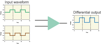
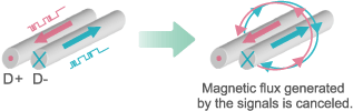
Differential transmission technology was adopted to resolve these issues. The differential transmission method uses two signal lines to flow opposite-phase currents, and performs transmission using the potential difference between the signal lines. External noise affects the + side and - side signal lines equally, and differential transmission considers only the potential difference between the signal lines, so the effect of the noise is canceled, making it more difficult for operation errors to occur.
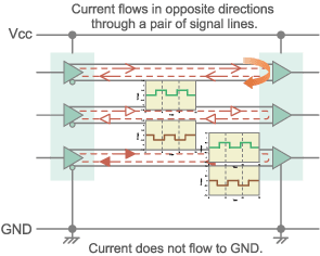

In addition, since the currents flow in opposite directions from each other, the magnetic flux is canceled, reducing the EMI noise due to signal harmonics.
Differential transmission lines do not easily emit EMI noise, but a certain level of common mode noise is unavoidable due to fluctuation of the driver IC reference potential and asymmetry of the transmission lines. For this reason, there are also requests for parts that reduce common mode noise; common mode choke coils were developed as noise filters. In addition to EMI noise countermeasure effects, common mode choke coils also act as transformers to correct signal asymmetry, so there are also waveform-shaping effects. Murata prides itself in having contributed to the development of differential transmission through its noise countermeasure parts.
Person in charge:
Toshiro Tsubouchi, EMI Division, Component Business Unit, Murata Manufacturing Co., Ltd.
The information presented in this article was current as of the date of publication. Please note that it may differ from the latest information.