Noise Suppression Products / EMI Suppression Filters / ESD Protection Devices
Noise Suppression Filter Guide
Previously, we introduced noise countermeasure parts mounted on a board as part of the electronic circuit. This time we introduce noise countermeasure parts that do not require mounting on a board. (Although they are sometimes fixed to the board...)
As previously introduced, when commercializing an electronic device, it is necessary to check that the noise emitted from the device satisfies the EMI regulations. However, the final check cannot be performed until the device design is complete. Recently, experience concerning designs that do not emit noise is increasing, and various measures are being implemented beforehand to prevent the generation of noise, but of course the effects cannot be known until the final test. There is no problem as long as the noise level is within the regulation value as expected at this point, but the test results sometimes exceed the regulation value. When the delivery date is near, there is no time to change the board, so parts such as ferrite cores that enable countermeasures without changing the board come in handy.
Ferrite cores are ceramic magnetic bodies consisting of ferrites (soft ferrites) processed into various shapes. Formerly, coils were often made by winding conducting wires around a ring-shaped ferrite core, so ferrite used for noise countermeasures is likewise called a ferrite core.
Ferrites include Mn-Zn ferrite and Ni-Zn ferrite according to the composition. Mn-Zn ferrite is conductive, so it requires insulation work, and Ni-Zn ferrite has better high-frequency characteristics. For these and other reasons, Ni-Zn ferrite is often used for noise countermeasures.
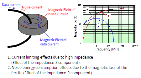
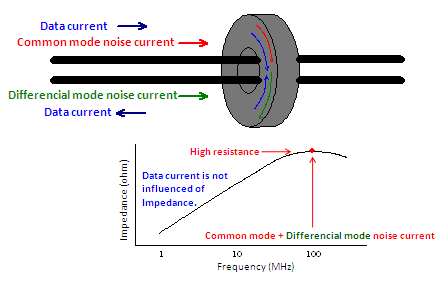
Ferrite cores come in various shapes, but most are ring-shaped. By passing conducting wires through the hole of the ring, the conducting wires and the ferrite core form a coil (inductor). This coil (inductor) is based on the same principle as that of an electronic part inductor, so the impedance increases together with the frequency as shown in Figure 1. Therefore, the coil functions as a low-pass filter that blocks high-frequency current, enabling attenuation of high-frequency noise. Furthermore, the use of a ferrite core also provides an additional effect. When current flows to an inductor comprising a ferrite core, magnetic flux is generated in the ferrite core, and the current energy is converted into magnetic energy. However, when the current changes, this magnetic flux is converted back into current by electromagnetic induction. At this time, not all of the magnetic flux energy is returned to current energy, and some is lost as magnetic loss. (This is called "hysteresis loss.") As a result, part of the noise current passing through the conducting wires is lost as magnetic loss, reducing the energy. The right side of Figure 1 shows the impedance characteristics of a coil with conducting wires passed through a ferrite core. The impedance of a normal coil consists mostly of the reactance (X) component, but when a ferrite core is used, the resistance (R) component becomes extremely large. This is a result of selecting ferrite materials suitable for noise countermeasures, and causes the noise energy consumption effect due to magnetic loss to account for a larger portion of the noise removal effect of the ferrite core than the current limiting effect of high impedance.
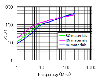
The noise removal performance of ferrite cores varies according to the ferrite materials and shape.The magnetic permeability changes according to the ferrite materials, so the impedance also differs. In addition, the ratio between the resistance component and reactance component of the impedance also differs according to the materials. However, the materials of ferrite cores sold as noise countermeasures are blended specially for noise countermeasures, so there is no great difference in the characteristics regardless of the material selected.
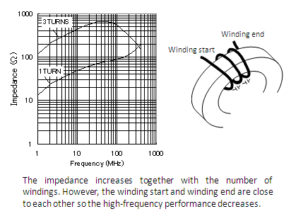
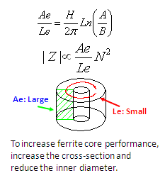
The inductance increases (proportionally to the square of the number of windings) together with the number of times the conducting wire is passed through the ring core (number of windings). However, when the conducting wire is wrapped around the core, the winding start (entrance) and winding end (exit) come close to each other and have floating capacitance between them. High-frequency noise is conveyed via this floating capacitance area, which is a factor lowering the high-frequency performance. Therefore, in consideration of the target frequencies for noise reduction, the number of windings must either be increased to target the low-frequency range, or reduced to target the high-frequency range.
In addition, the ferrite core dimensions affect the performance as shown in Figure 4. Therefore, a ring core with the smallest inner diameter and widest cross-sectional area possible should be selected.
Due to their convenience, ferrite cores are often used on cables. However, these cables include interface cables, power cables, and other multiple conducting wires that run in parallel, so common mode noise is often an issue. Common mode choke coils are an effective noise countermeasure in these cases, and common mode choke coil functions can be achieved by passing the cables together through a single ferrite core. For example, in case of an interface cable that has multiple signal lines wired to a single end, it is difficult to wire common mode choke coils. However, common mode choke coil functions can be easily achieved by passing all of the interface cable wires together through a ferrite core.
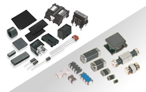
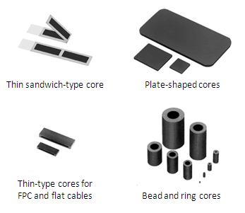
Thus far we have introduced ring-shaped ferrite cores, but various other ferrite core shapes have also been commercialized. These include cores with wide and thin shapes that match the shapes of flat cables and flexible printed circuits (FPC), and divided cores that are assembled around cables to eliminate the work of passing the cables through the cores. In addition, simple plate-shaped cores that are not rings are also provided. These plate cores are attached over ICs and other locations that emit electromagnetic waves, and aim for radio wave absorption effects by attenuating the electromagnetic waves passing through the plate core by the magnetic loss of the ferrite.
*The information presented in this article was current as of the date of publication. Please note that it may differ from the latest information.